


Pre-Installation
976-0043-01-02 3–7
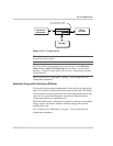
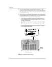
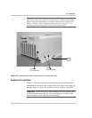
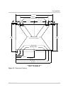
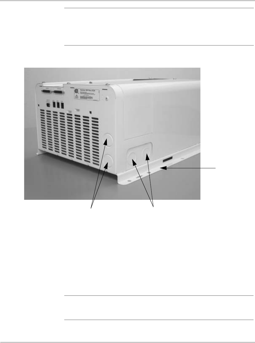
Figure 3-2
Serial Number Sticker and Knockout Locations and Sizes
Knockout Preparation
Remove your choice of knockouts from the chassis to facilitate conduit
installation for wire runs. This is much easier to do prior to mounting the
inverter. Figure 3-2 shows the locations and sizes of chassis knockouts.
Important: The exclamation symbol below the CSA logo on the certification
label indicates the need to add overcurrent protection. It shall be installed at the
battery as part of the installation in accordance with your local electrical code.
Table 2-3, “Battery Cable to Maximum Breaker/Fuse Size” on page 2–15
specifies the type and rating of the overcurrent protection needed.
3/4 and 1”
Dual-knockouts
Serial
Number
Sticker
3/4 and 1”
Dual-knockouts
Important:
Ensure there are no metal shavings left in the inverter after
removing the knockouts. Be sure to install bushings or conduits in the
knockout holes to protect the wires from damage.