976-0043-01-02 xix
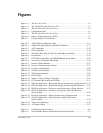
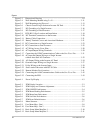
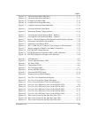
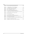
Figure 1-1 The Sine Wave Plus - - - - - - - - - - - - - - - - - - - - - - - - - - - - - - - - - - - - - -1–3
Figure 1-2 The Front Side of the Sine Wave Plus - - - - - - - - - - - - - - - - - - - - - - - - - -1–3
Figure 1-3 The AC side of the Sine Wave Plus - - - - - - - - - - - - - - - - - - - - - - - - - - - -1–4
Figure 1-4 Certification Label - - - - - - - - - - - - - - - - - - - - - - - - - - - - - - - - - - - - - - -1–5
Figure 1-5 The DC side of the Sine Wave Plus - - - - - - - - - - - - - - - - - - - - - - - - - - - -1–6
Figure 1-6 Battery Temperature Sensor (BTS) - - - - - - - - - - - - - - - - - - - - - - - - - - - -1–7
Figure 1-7 External Output Circuit Breaker - - - - - - - - - - - - - - - - - - - - - - - - - - - - - -1–8
Figure 2-1 AWG Wire Size Reference Chart - - - - - - - - - - - - - - - - - - - - - - - - - - - -2–13
Figure 2-2 Sample Warning Sticker for Backfeed Conditions - - - - - - - - - - - - - - - - -2–17
Figure 2-3 AC Conduit Box - - - - - - - - - - - - - - - - - - - - - - - - - - - - - - - - - - - - - - -2–22
Figure 2-4 DC Conduit Box - - - - - - - - - - - - - - - - - - - - - - - - - - - - - - - - - - - - - - -2–23
Figure 2-5 Sine Wave Plus with AC and DC Conduit Boxes Installed - - - - - - - - - - -2–23
Figure 2-6 Fuse Blocks- - - - - - - - - - - - - - - - - - - - - - - - - - - - - - - - - - - - - - - - - - -2–24
Figure 2-7 DC250 Disconnect Box and TM500A Battery Status Meter - - - - - - - - - -2–25
Figure 2-8 Accessories for Remote Monitoring - - - - - - - - - - - - - - - - - - - - - - - - - -2–26
Figure 2-9 Inverter Control Module - - - - - - - - - - - - - - - - - - - - - - - - - - - - - - - - - -2–27
Figure 2-10 Inverter Communications Adapter - - - - - - - - - - - - - - - - - - - - - - - - - - -2–27
Figure 2-11 Generator Start Module- - - - - - - - - - - - - - - - - - - - - - - - - - - - - - - - - - -2–28
Figure 2-12 Auxiliary Load Module- - - - - - - - - - - - - - - - - - - - - - - - - - - - - - - - - - -2–28
Figure 2-13 T240 Autotransformer- - - - - - - - - - - - - - - - - - - - - - - - - - - - - - - - - - - -2–29
Figure 2-14 ISC-S Cable - - - - - - - - - - - - - - - - - - - - - - - - - - - - - - - - - - - - - - - - - -2–29
Figure 2-15 Xantrex C-Series Charge Controllers- - - - - - - - - - - - - - - - - - - - - - - - - -2–31
Figure 2-16 PV Ground Fault Protection (PVGFP) - - - - - - - - - - - - - - - - - - - - - - - - -2–31
Figure 2-17 Off-Grid Application – Renewable Energy System using a Single Inverter 2–33
Figure 2-18 Off-Grid Application – Renewable Energy System using Dual Inverters - -2–35
Figure 2-19 Off Grid Application - Generator-only System using a Single Inverter - - -2–37
Figure 2-20 Off Grid Application – Generator-only System using Dual Inverters,
Series-stacked - - - - - - - - - - - - - - - - - - - - - - - - - - - - - - - - - - - - - - - - -2–39
Figure 2-21 On-Grid Application – Backup System using a Single Inverter - - - - - - - -2–41
Figure 2-22 On-Grid Application – Backup System using Dual Inverters,
Series-stacked - - - - - - - - - - - - - - - - - - - - - - - - - - - - - - - - - - - - - - - - -2–43
Figure 2-23 Time-of-Use Metering - - - - - - - - - - - - - - - - - - - - - - - - - - - - - - - - - - -2–45
Figure 2-24 AC Support Mode - - - - - - - - - - - - - - - - - - - - - - - - - - - - - - - - - - - - - -2–47
Figure 3-1 Certification Label Location- - - - - - - - - - - - - - - - - - - - - - - - - - - - - - - - -3–6
Figure 3-2 Serial Number Sticker and Knockout Locations and Sizes- - - - - - - - - - - - -3–7
Figures


