


Multi-wire Branch Circuit Wiring
F–4 976-0043-01-02
Identifying Multi-wire Branch Circuits
Identifying
characteristic
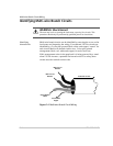
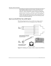
Multi-wire branch circuits can be identified by removing the cover on the
load center and inspecting the wiring. Conventional 120 Vac circuits are
identified by a 2-wire-plus-ground (black, white, and copper) “romex” for
each circuit. Multi-wire branch circuits use a 3-wire-plus-ground
arrangement (black, red, white and copper) for each circuit run.
If this arrangement exists in the panel and it is being powered by a stand-
alone 120 Vac inverter, a potential fire hazard exists! For safety, these
circuits must be rewired to meet code.
WARNING: Shock Hazard
The next step involves opening the load center, exposing live circuits. This
procedure should only be performed by qualified persons or electricians.
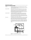
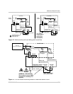
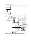
Figure F-4
Multi-wire Branch Circuit Wiring
Ground Bare
Copper
S
ingle Neutral
White
Red From L2
Breaker
Red From L1
Breaker
To Branch Circuits