Installation
3–26 976-0043-01-02
AC Wiring
This section describes:
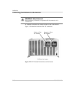
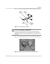
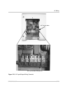
• “Accessing the AC Terminal Block and Ground Bar” on page 3–28,
and
• “AC Wiring for Single Inverter Systems” on page 3–30.
Disregard installation sections and illustrations that do not apply to your
configuration (for example, installing utility panels in Off-Grid
applications or wiring for generators when no generator is used, etc.)
Before wiring the input of the inverter, refer to Table 3-1 below for
Maximum AC wire sizes and disconnects devices. Determine the correct
AC wire size and disconnect size to use for installation.
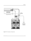
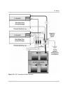
The Sine Wave Plus inverter has two AC inputs, AC1 GRID and
AC2 GEN. The AC1 GRID input is intended to be used with grid power
and the inverter can do “grid features” (BX Mode, time-of-day usage)
with this input. The AC2 GEN input is intended to be used with AC
generators and the inverter can do “generator features” (auto-start) with
this input.
The inverter will accept and use AC power on either of these inputs. Be
aware that the inverter menu structure is organized and the features are
optimized around AC1 receiving grid power and AC2 receiving generator
power. If you install grid power on the AC2 GEN input or generator
power on the AC1 grid input the results may be different that expected or
noted in your users manual.
Examples of using an input source other than its factory designation.
1. An off-grid site with two generators, an auto-start generator
connected to AC2 and spare manual-start generator connected to
AC1.
2. An on-grid site with a generator wired into a main grid/generator
transfer switch. The AC2 input would need to be used to utilize the
auto start feature of the inverter. Note: the inverter's “grid features”
would not be available in this wiring configuration.”


