


Inverter Control Module Features
976-0043-01-02 5–3
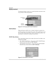
The Inverter Control Module (ICM)
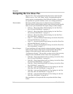
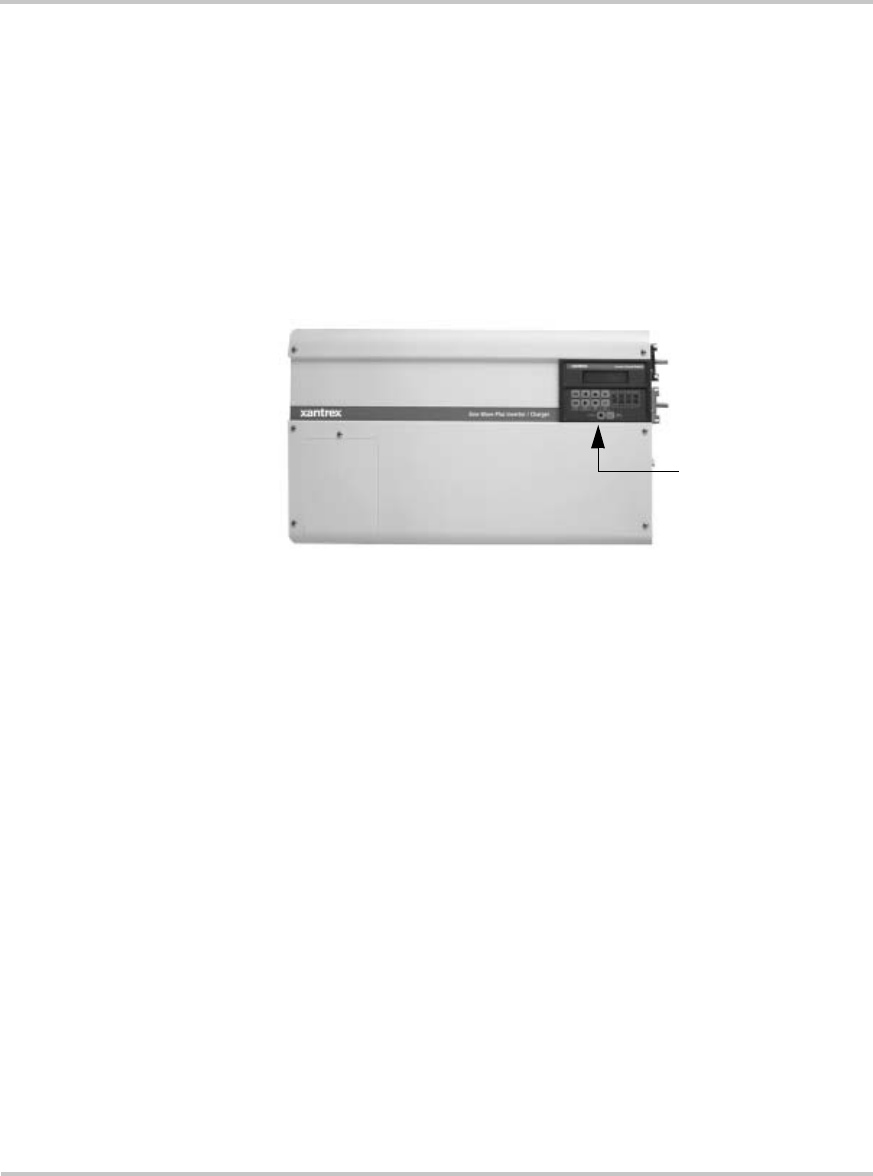
The ICM is located on the front panel of the Sine Wave Plus. It’s used to
display status information regarding the operation and performance of the
unit. It is also used to access the “Basic Setup”, “Advanced Setup”, and
“User Menus”. All settings (except for Time of Day) can be saved in non-
volatile memory so they are not lost when DC power is removed from the
inverter.
If a remote ICM is installed, you may do all the same programming from
the remote control module instead.
Inverter Control Module Features
There are nine push-buttons, eight Light Emitting Diodes (LEDs), one
contrast adjustment and one Liquid Crystal Display (LCD) on the front of
the ICM. The push-buttons are grouped into sets depending on their
function. The LEDs also are grouped by function.
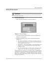
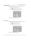
The display
The system information, menu items, and set points are all displayed on a
Liquid Crystal Display (LCD). The contrast of the display can be adjusted
by the Contrast Adjustment screw at the bottom of the panel.
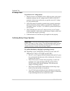
The cursor
When navigating through the menu system, the selected item is indicated
in the LCD by a shaded, flashing box over the first letter/number of the
set point. This special highlighting is called the "cursor". Pressing the
SET POINT buttons will move the cursor left (–) or right (+) within the
available options.
Figure 5-1
ICM Display Location
ICM Display