


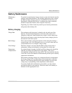

Battery Configurations
976-0043-01-02 C–9
Battery Configurations
The battery bank must be wired to match the inverter’s DC input voltage
specifications (24 or 48 Vdc). In addition, the batteries can be wired to
provide additional run time. The various wiring configurations are:
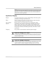
Series Wiring batteries in series increases the total bank output voltage. This
voltage MUST match the DC requirements of the inverter or inverter and/
or battery damage may occur.
Parallel Wiring the batteries in parallel increases the total run time the batteries
can operate the AC loads. The more batteries connected in parallel the
longer the loads can be powered from the inverter.
Series-Parallel Series-parallel configurations increase both the battery voltage (to match
the inverter’s DC requirements) and run-time for operating the AC loads.
This voltage must match the DC requirements of the inverter.
Batteries with more than two or three series strings in parallel often
exhibit poor performance characteristics and shortened life.
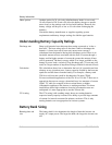
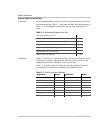
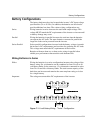
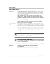
Wiring Batteries in Series
Effect Wiring the batteries in a series configuration increases the voltage of the
battery string. Six-volt batteries can be combined to form 24-volt or 48-
volt battery banks. In the same way, 12-volt batteries connected in series
form 24-volt and 48-volt battery banks. The total current capacity of the
bank does not increase and remains the same amp-hour rating as it does
for a single battery.
Important The voltage must match the DC requirements of the inverter.
Figure C-1
6-volt Battery Wiring - “Series” Configuration
+ - + -
6 V 6 V
+ -
24 V INVERTER
(T otal batter y capaci ty = 100 Ah)
+ - +
6 V 6 V
-
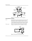
+ - + -
6 V 6 V
+ -
48 V INVERTER
(Total battery capacity = 100 Ah)
+ - + -
6 V 6 V
+ - + -
6 V 6 V
+ - + -
6 V 6 V