Inverter Specifications
A–6 976-0043-01-02
Theory of Operation
The Sine Wave Plus employs a patented inverter design. This design uses
a combination of three transformers, each with its own low frequency
switches, coupled in series and driven by separate interconnected micro-
controllers. In essence, it is three inverters linked together by their
transformers.
Sine Wave Plus
Waveform
By mixing the outputs from the different transformers, a sine wave is
produced. This waveform is shown in Figure A-2, “Sine Wave Plus
Inverter Output Waveform” on page A–7. Notice the “steps” form a
staircase that is shaped like a sine wave. The total harmonic distortion in
this sine wave approach is typically 3-5%. The multi-stepped output is
formed by modulation of the voltage through mixing of the transformers
in a specific order. Anywhere from 34-52 “steps” per AC cycle are
present in the waveform. The heavier the load or lower DC input voltage
the more steps there are in the waveform.
This type of inverter solves many of the problems associated with high
frequency or ferroresonant sine wave inverters. The low frequency
method described has excellent surge ability, high efficiency (typically 85
to 95%), good voltage and frequency regulation, and low total harmonic
distortion.
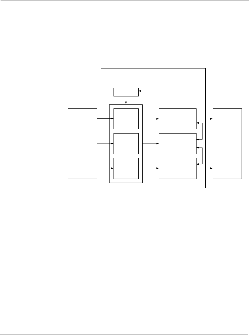
Figure A-1
Sine Wave Plus
Simple Block Diagram
Batteries
Low Frequency
H-Bridge
Low Frequency
H-Bridge
Low Frequency
H-Bridge
Transformer
Transformer
Transformer
AC Loads
Micro-controllers
Bridges are “mixed” by
Micro-controllers
controlling the H-Bridges
Sine Wave Plus Inverter Charger


