Theory of Operation
976-0043-01-02 A–7
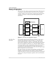
The inverter runs in two basic formats: as a stand-alone inverter
(converting DC to AC), or as a parallel inverter (with its output
synchronized to another AC source). In inverter mode, only 60 Hz
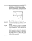
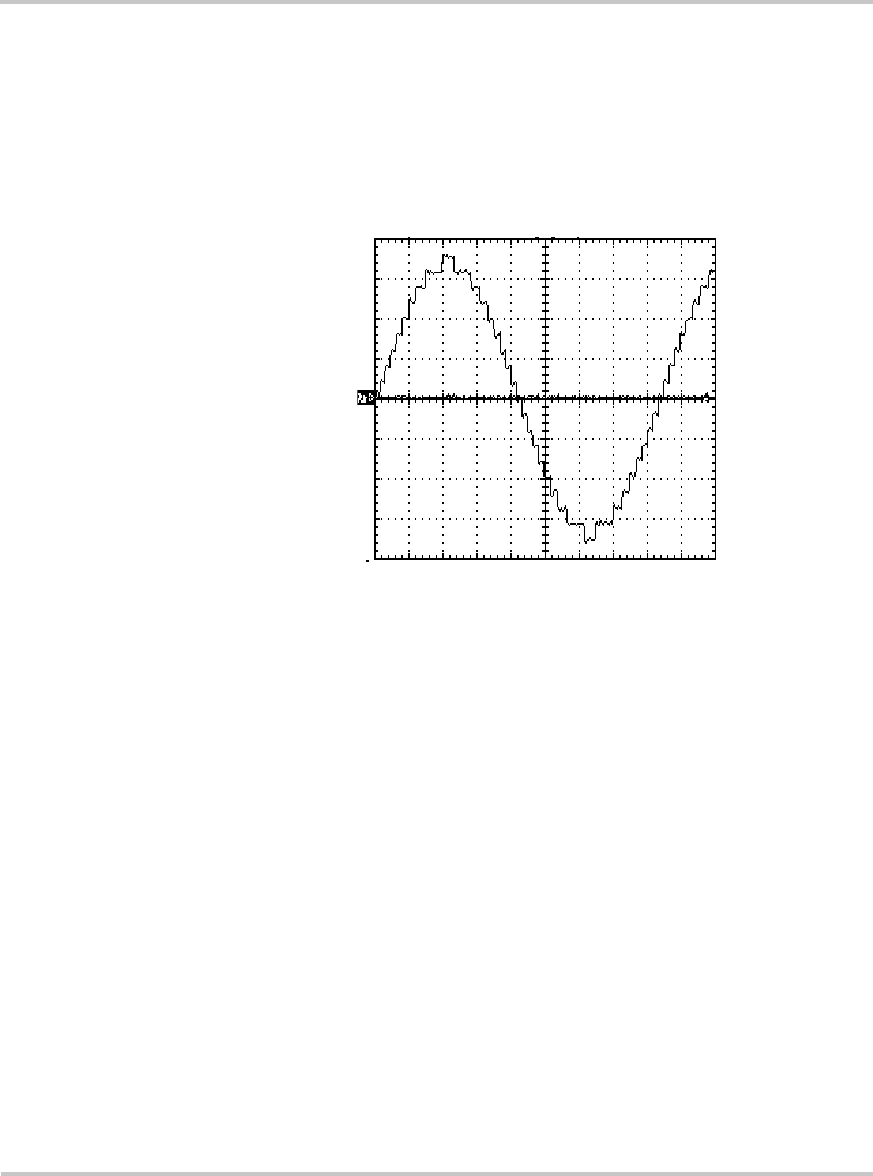
waveforms are created. As the battery voltage rises, waveforms with
progressively fewer steps are generated. More steps are used when battery
voltage decreases. Since the battery voltage tends to drop with increased
load, the waveform has increased number of steps with heavier AC loads.
Synchronized with
other AC sources
The inverter is able to synchronize with other AC sources before
connecting it to the AC load. The frequency of the AC source is tracked
and the inverter constantly adjusts its frequency to maintain a lock. A
normally open contactor is used to parallel the inverter’s output and the
AC source.
Bi-Directional
Topology
The inverter’s power topology is bi-directional. If the waveform created
by the inverter has a higher voltage than the paralleled AC source, then
power flows from the batteries to the load. If the waveform generated has
a lower voltage than the AC source, power flows from the source to the
battery.
Waveform Size The various modes of operation use different algorithms for determining
the size of the waveform to be created by the inverter. In battery charger
mode, for example, waveforms smaller than the AC source are created to
cause current to flow into the batteries. This process is fully regulated to
provide a three-stage charge cycle. If the level of AC current exceeds the
user programmed generator or grid size, and then the inverter will switch
to a generator support mode and create waveforms that are larger than the
AC source. This causes power to flow from the batteries to the AC loads
to prevent overloading of the AC source.
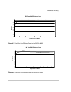
Figure A-2
Sine Wave Plus
Inverter Output Waveform


