


Installation
3–30 976-0043-01-02
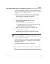
AC Wiring for Single Inverter Systems
There are three major steps in the procedure for AC wiring of
single-inverter systems. They are described in detail on the
following pages:
1. “Install AC Output Wiring to the Inverter AC Distribution Panel” on
page 3–33.
2. “Install Generator Wiring to the Inverter” on page 3–35.
3. “Install Utility Wiring to the Inverter Input (On-Grid Applications
only)” on page 3–38.
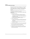
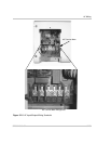
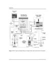
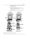
The completed wiring is shown in Figure 3-18, “AC Input and Output
Wiring to a Single Inverter with an Auto-Start AC Generator” on page 3–
32. This illustration shows an auto-start generator; a manual-start
generator would be wired in the same way except that there would be no
GSM. The T240 Autotransformer and generator disconnect switch are
optional, but the generator disconnect switch is strongly recommended.
Manual and Auto Start Generators
Some generators must be started manually at the generator. These kinds
of generators do not require the use of the Generator Start Module (GSM).
Some generators allow automatic starting. In this case, the addition of the
GSM is required for the inverter to start/stop the generator and to transfer
the AC input voltage to the inverter.
Exact wiring instructions cannot be given for auto-start generators as the
wiring configuration may vary depending on the type of auto-start circuit
used.
See “Generator Starting Scenarios” on page 7–23 and the GSM
Installation Guide for specific installation instructions for connecting a
generator to the GSM.
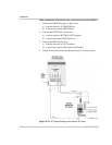
Important:
Wiring to the utility panel is performed after all other connections
have been made in the inverter. Be sure to make all the other connections to the
inverter first (steps 1 and 2 above).