


POSTSCRIPT EMULATION
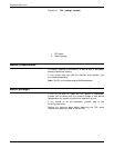
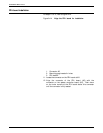
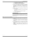
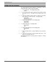
13. Align the mounting pegs with the holes in the PDL board.
Press down firmly on either side of the holes on the PDL
board until the pegs snap into position. (Refer to figure A4-
5.) Moderate, even pressure must be applied to the PDL
board to seat it correctly in the connector.
Figure A4-5. PDL board correctly installed
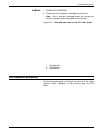
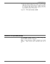
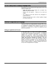
Contents of the coprocessor package
The coprocessor package contains a printed wiring board
assembly (PWBA), as pictured in figure A4-6.
Note: In these instructions, a PWBA is referred to as a board
(example: system controller board, coprocessor board, and so
on).
XEROX 4213 LASER PRINTER USER GUIDE A4-7