


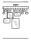

POSTSCRIPT EMULATION
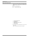
1. Coprocessor board inserted at 30° angle
2. Coprocessor board tilted toward upright position
3. Coprocessor board locked in upright position
4. With firm, even pressure over the length of the coprocessor
board, tilt it to a vertical position until the edges of the board
snap behind the locking tabs of the connector (refer to
figure A4-9).
Note: A slight force may be required to engage the locking
tabs.
5. Check to make sure the coprocessor board is securely held
by the locking tabs.
• If the board tilts easily back to the 30° angle, repeat
steps 1 to 4.
• If the board does not move, installation is complete.
For installation of SIMMS, see A5.
Install additional options
If you purchased additional options for your printer, you can
install them at this time while the system controller board is out
of the printer. If there are no additional options to be installed,
continue with step 6.
System controller board reinstallation
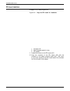
6. Place the system controller board into the receiving rails of
the printer.
7. For reinstallation of the system controller board, reverse the
removal process in steps 1 to 6 of the PDL installation
procedure.
8. Print a configuration sheet. If the sheet prints and indicates
the PDL PWB and coprocessor are present, installation was
successful.
Caution: Cable connectors may interfere with the
reinstallation of the system controller board; therefore, route
them carefully.
XEROX 4213 LASER PRINTER USER GUIDE A4-11