


Verifying the Wireless Network 151
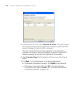
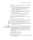
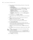
3 In the Show RF coverage using listbox, select how you want to display the
coverage:
Baseline Association Rate—Coverage is shown based on the MAP
radio baseline association rate. The baseline association rate is the
typical data rate the radio is expected to support for client
associations. (The baseline association rate is specified during
planning, on a coverage area basis.)
Data Rate—Coverage is shown in colored bands that represent each
of the data transmit rates supported by the radio. These rates are
standard for each radio type.
RSSI—Coverage is shown based on the received signal strength
indication (RSSI) of the radio’s signal heard by other radios.
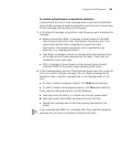
If you need to make adjustments, do the following:
1 Move the MAPs, or increase the transmit power levels to provide better
coverage.
2 Create more MAPs, and place them on the floor.
3 Modify the coverage area so that the capacity requirements are higher.
If you manually add MAPs to a coverage area, they might be moved or
removed when you next perform Compute and Place.
If you have already installed a MAP in the network and you want to add it
to the coverage area, see “Adding New MAPs that Are Already Installed
to the Network Plan” on page 480.
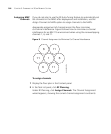
Placing RF
Measurement Points
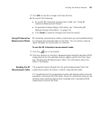
An RF measurement point on the floor plan simulates the measurement
of signal strength from all MAPs at a specific position on the floor. Placing
RF measurement points is optional. RF measurement points are helpful
for verifying the wireless network. You can place as many RF
measurement points as you want. You can place them anywhere and
move them later. Information from RF measurement points is included in
a floor’s work order.
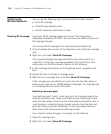
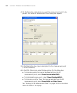
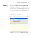
To place an RF measurement point
1 Display the floor plan in the Content panel.
2 In the Task List panel, click Tools.
3 In the Coverage Area task group, under Wiring Closet/Misc, click the
(Insert Measurement Point) icon.