


1-87
Making Measurements
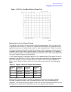
Using Ripple Limits to Test a Device
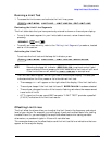
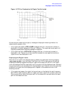
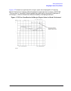
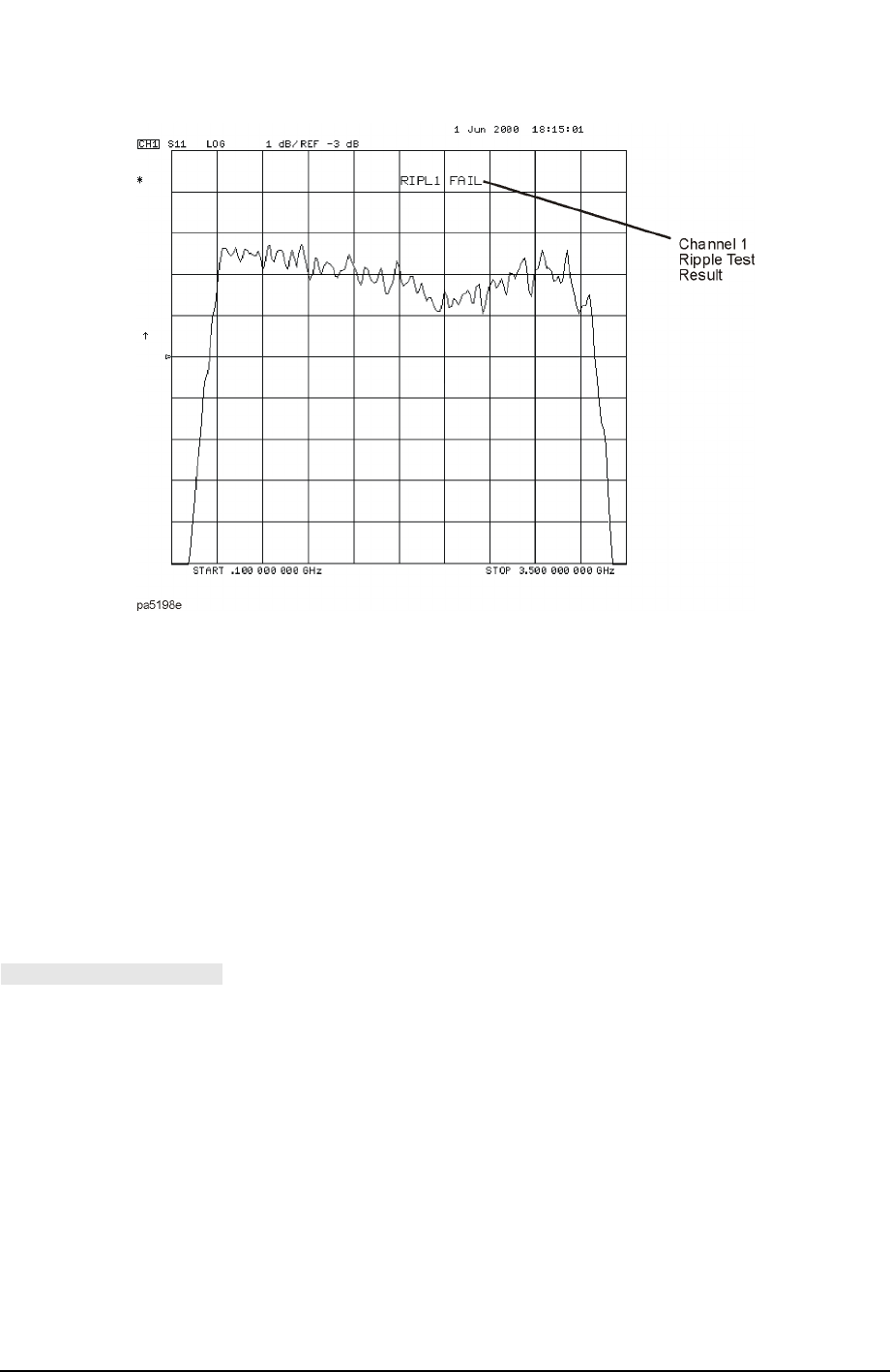
Figure 1-67 Filter Passband with Ripple Test Activated
As the analyzer measures the ripple, a message is displayed indicating whether the
measurement passes or fails:
• If the ripple test passes, a RIPLn PASS message (where n = the channel number) is
displayed in the color assigned to Channel 1 Memory. The ripple test must pass in all
frequency bands before the pass message is displayed.
• If the ripple test fails, a RIPLn FAIL message (where n = the channel number) is
displayed in red. The portion of the trace that exceeds the user-specified maximum
ripple value is also displayed in red.
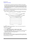
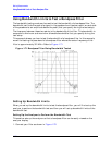
Displaying the Ripple Limits
After the list of ripple limits has been set up, display the ripple test limits by pressing
from the Ripple Test Menu until ON is displayed on the softkey.
Pressing this softkey toggles the analyzer ripple limits display on and off. If the ripple
limits are displayed and the ripple test is off, the ripple limits are displayed near the top of
the graticule and are not compared with the displayed trace. However, once the ripple test
is started, the ripple limits are displayed with respect to the measured trace in the
following manner:
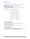
• If the ripple test passes, the ripple limits are drawn on the display for each frequency
band. Within each frequency band, an upper and lower ripple limit is drawn such that
they are equidistant above the upper point of the measured trace and below the lower
point of the measured trace.
RIPL LIMIT on OFF