


7-62
Operating Concepts
Modifying Calibration Kits
The following is a description of the softkeys located within the specify offset menu:
• allows you to specify the one-way electrical delay from the
measurement (reference) plane to the standard, in seconds (s). (In a transmission
standard, offset delay is the delay from plane to plane.) Delay can be calculated from the
precise physical length of the offset, the permittivity constant of the medium, and the
speed of light.
In coax, group delay is considered constant. In waveguide, however, group delay is
dispersive, that is, it changes significantly as a function of frequency. Hence, for a
waveguide standard, offset delay must be defined as though it were a TEM wave
(without dispersion).
• allows you to specify energy loss, due to skin effect, along a one-way
length of coax offset. The value of loss is entered as ohms/nanosecond (or Giga
ohms/second) at 1 GHz. (Such losses are negligible in waveguide, so enter 0 as the loss
offset.)
• allows you to specify the characteristic impedance of the coax offset.
(Note: This is not the impedance of the standard itself.) For waveguide, the offset
impedance as well as the system Z0 must always be set to 1Ω.
• allows you to define the lowest frequency at which the
standard can be used during measurement calibration. In waveguide, this must be the
lower cutoff frequency of the standard, so that the analyzer can calculate dispersive
effects correctly (see ).
• allows you to define the highest frequency at which the
standard can be used during measurement calibration. In waveguide, this is normally
the upper cutoff frequency of the standard.
• defines the standard (and the offset) as coaxial. This causes the analyzer to
assume linear phase response in any offsets.
• defines the standard (and the offset) as rectangular waveguide. This
causes the analyzer to assume a dispersive delay (see ).
Label Standard Menu
This menu allows you to label (reference) individual standards during the menu-driven
measurement calibration sequence. The labels are user-definable using a character set
shown on the display that includes letters, numbers, and some symbols, and they may be
up to ten characters long. The analyzer will prompt you to connect standards using these
labels, so they should be meaningful to you, and distinct for each standard.
By convention, when sexed connector standards are labeled male (m) or female (f), the
designation refers to the test port connector sex, not the connector sex of the standard.
Specify Class Menu
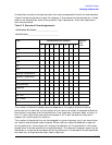
Once a standard has been defined, it must be assigned to a standard "class." This is a
group of from one to seven standards that is required to calibrate for a single error term.
The standards within a single class can be assigned to the locations listed in Table 7-2
according to their standard reference numbers.
OFFSET DELAY
OFFSET LOSS
OFFSET Z0
MINIMUM FREQUENCY
OFFSET DELAY
MAXIMUM FREQUENCY
COAX
WAVEGUIDE
OFFSET DELAY