


1-44
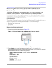
Making Measurements
Measuring Electrical Length and Phase Distortion
You may also want to select settings for the number of data points, averaging, and IF
bandwidth.
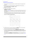
3. Substitute a thru for the device and perform a response calibration by pressing:
4. Reconnect your test device.
5. To better view the measurement trace, press:
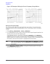
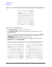
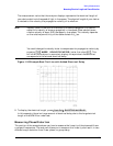
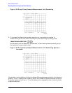
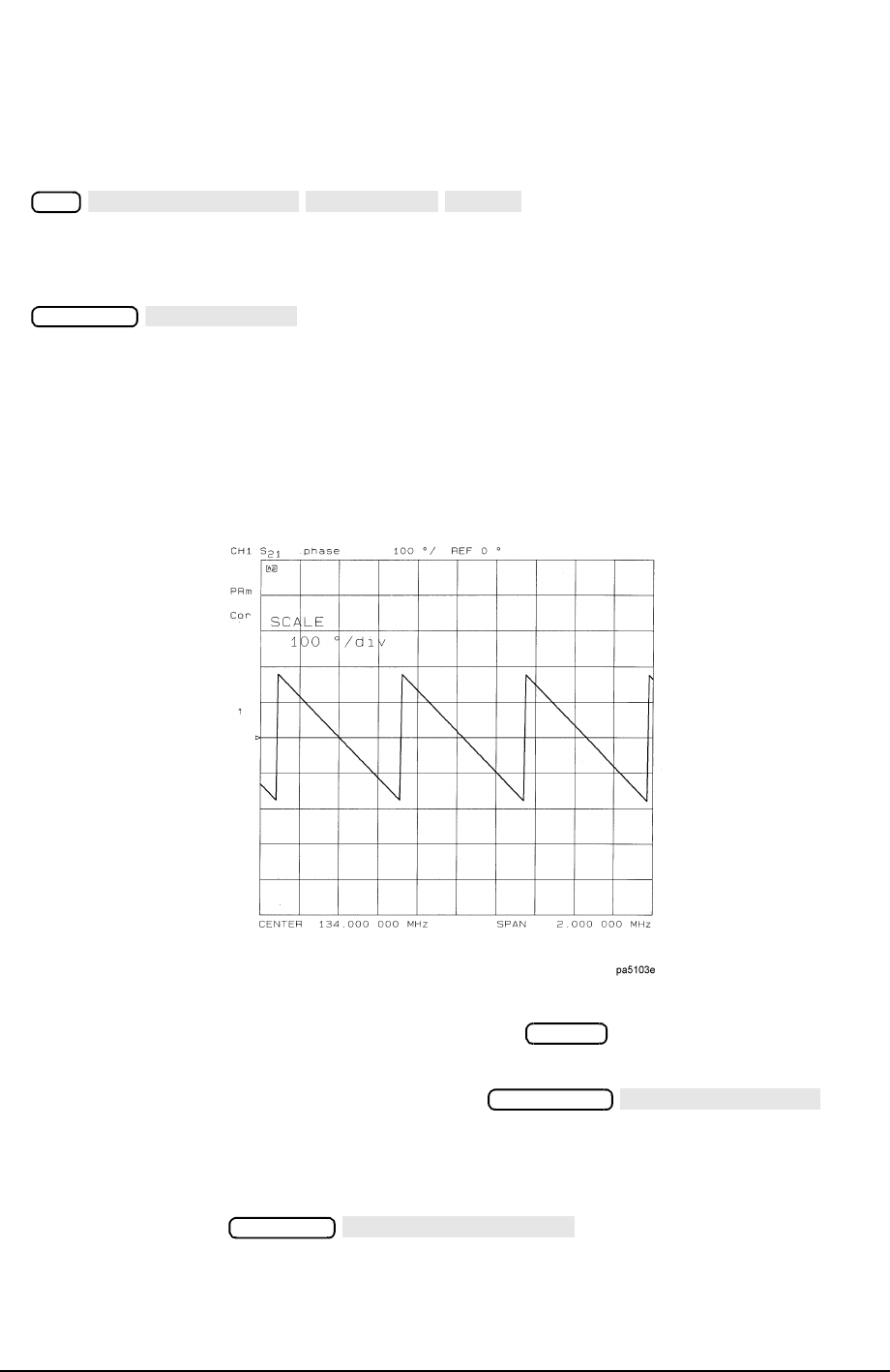
Notice that in Figure 1-34 the SAW filter under test has considerable phase shift within
only a 2 MHz span. Other filters may require a wider frequency span to see the effects
of phase shift.
The linearly changing phase is due to the device’s electrical length. You can measure
this changing phase by adding electrical length (electrical delay) to compensate for it.
Figure 1-34 Linearly Changing Phase
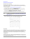
6. To place a marker at the center of the band, press and turn the front panel
knob, or enter a value from the front panel keypad.
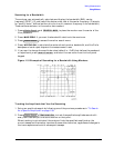
7. To activate the electrical delay function, press .
This function calculates and adds in the appropriate electrical delay by taking a ±10%
span about the marker, measuring the ∆Φ, and computing the delay as the negative of
∆Φ / ∆ frequency.
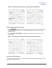
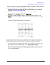
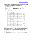
Alternatively, press and turn the front panel knob
to increase the electrical length until you achieve the best flat line, as shown in Figure
1-35.
Cal
CALIBRATE MENU
RESPONSE
THRU
Scale Ref
AUTO SCALE
Marker
Marker Fctn
MARKER
→
DELAY
Scale Ref
ELECTRICAL DELAY