


3-7
Making Time Domain Measurements
Making Transmission Response Measurements
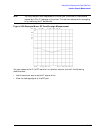
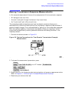
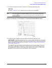
11.To activate the gating function to remove any unwanted responses, press:
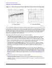
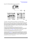
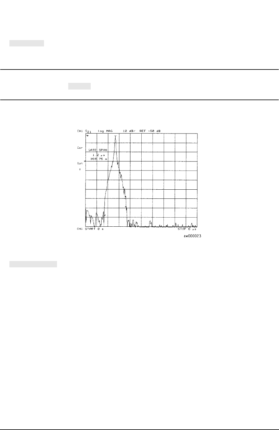
As shown in Figure 3-4, only response from the main path is displayed.
NOTE You may remove the displayed response from inside the gate markers by
pressing and turning the front panel knob to exchange the "flag"
marker positions.
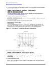
Figure 3-4 Gating in a Time Domain Transmission Example Measurement
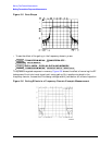
12.To adjust the gate shape for the best possible time domain response, press
and select between minimum, normal, wide, and maximum. Each gate
has a different passband flatness, cutoff rate, and sidelobe levels. A detailed discussion
of gating and gate shape selections is located in "Gating" on page 3-35 and "Selecting
Gate Shape" on page 3-36.
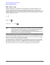
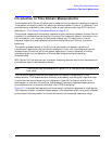
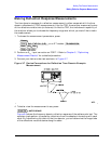
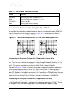
The passband ripple and sidelobe levels are descriptive of the gate shape. The cutoff
time is the time between the stop time (−6 dB on the filter skirt) and the peak of the
first sidelobe, and is equal on the left and right side skirts of the filter. The minimum
gate span is just twice the cutoff time because it has no passband.
GATE ON
SPAN
GATE SHAPE