


7-76
Operating Concepts
TRL*/LRM* Calibration (ES Models Only)
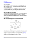
The TRM calibration technique is related to TRL with the difference being that it bases the
characteristic impedance of the measurement on a matched Z
O
termination instead of a
transmission line for the third measurement standard. Like the TRL thru standard, the
TRM THRU standard can either be of zero length or non-zero length. The same rules for
thru and reflect standards used for TRL apply for TRM.
TRM has no inherent frequency coverage limitations which makes it more convenient in
some measurement situations. Additionally, because TRL requires a different physical
length for the thru and the line standards, its use becomes impractical for fixtures with
contacts that are at a fixed physical distance from each other.
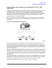
For information on how to modify calibration constants for TRL*/LRM*, and how to
perform a TRL or TRM calibration, refer to “Calibrating for Non-Coaxial Devices (ES
Analyzers Only)” on page 6-50.
TRL Options
The softkey accesses the TRL/LRM options menu. There are two
selections under this menu:
• (calibration Z
0
)
• (set reference)
The characteristic impedance used during the calibration can be referenced to either the
line (or match) standard ( ) or to the system ( ).
The analyzer defaults to a calibration impedance that is equal to the line (or match)
standard.
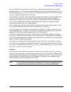
When the is selected, the impedance of the line (or match) standard is
assumed to match the system impedance exactly (the line standard is reflectionless). After
a calibration, all measurements are referenced to the impedance of the line standard. For
example, when the line standard is remeasured, the response will appear at the center of
the Smith chart. When is selected, the values entered for
(under menu) and (within the define standard menu) are ignored.
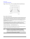
is selected when the desired measurement impedance differs from
the impedance of the line standard. This requires a knowledge of the exact value of the Z
0
of the line. The system reference impedance is set using under the calibration
menu. The actual impedance of the line is set by entering the real part of the line
impedance as the within the define standard menu. For example, if the line
was known to have a characteristic impedance of 51 Ω ( = 51 Ω), it could still
be used to calibrate for a 50 Ω measurement ( = 50 Ω). After a calibration, all
measurements would be referenced to 50 Ω, instead of 51 Ω. When the line standard is
remeasured, the center of the Smith chart is at the current value of (in this case,
50 Ω). Since only one value of offset Z
0
can be selected for the line standard, the value of Z
0
should be a constant value over the frequency range of interest in order to be meaningful.
TRL/LRM OPTION
CAL ZO:
SET REF:
CAL ZO: LINE ZO
CAL ZO: SYSTEM ZO
CAL ZO: LINE ZO
CAL ZO: LINE ZO
SET ZO
Cal
OFFSET ZO
CAL ZO: SYSTEM ZO
SET ZO
OFFSET ZO
OFFSET ZO
SET ZO
SET ZO