


7-68
Operating Concepts
TRL*/LRM* Calibration (ES Models Only)
TRL Terminology
Notice that the letters TRL, LRL, LRM, etc. are often interchanged, depending on the
standards used. For example, "LRL" indicates that two lines and a reflect standard are
used; "TRM" indicates that a thru, reflection and match standards are used. All of these
refer to the same basic method.
TRL* calibration is a modified form of TRL calibration. It is adapted for a receiver with
three samplers instead of four samplers. The TRL* calibration is not as accurate as the
TRL calibration because it cannot isolate the source match from the load match, so it
assumes load match and source match are equal. However, option 400 on the ES model
adds the fourth sampler and provides for a true TRL calibration.
How TRL*/LRM* Calibration Works
The TRL*/LRM* calibration used in the analyzer relies on the characteristic impedance of
simple transmission lines rather than on a set of discrete impedance standards. Since
transmission lines are relatively easy to fabricate (in a microstrip, for example), the
impedance of these lines can be determined from the physical dimensions and substrate’s
dielectric constant.
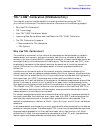
TRL* Error Model
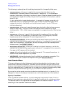
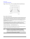
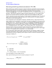
Figure 7-43 Functional Block Diagram for a 2-Port Error-Corrected
Measurement System
For the analyzer TRL* 2-port calibration, a total of 10 measurements are made to quantify
eight unknowns (not including the two isolation error terms). Assume the two
transmission leakage terms, E
XF
and E
XR
, are measured using the conventional technique.
The eight TRL error terms are represented by the error adapters shown in Figure 7-43.
Although this error model is slightly different from the traditional Full 2-port 12-term
model, the conventional error terms may be derived from it. For example, the forward
reflection tracking (E
RF
) is represented by the product of ε
10
and ε
01
.