


7-72
Operating Concepts
TRL*/LRM* Calibration (ES Models Only)
Transmission magnitude uncertainty = E
X
+ E
T
S
21
+ E
S
S
11
S
21
+ E
L
S
22
S
21
where:
E
D
= effective directivity
E
R
= effective reflection tracking
E
S
= effective source match
E
L
= effective load match
E
X
= effective crosstalk
E
T
= effective transmission tracking
S
xx
= S-parameters of the device under test
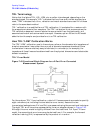
How True TRL/LRM Works (Option 400 Only)
The TRL implementation with Option 400 requires a total of fourteen measurements to
quantify ten unknowns as opposed to only a total of twelve measurements for TRL*. (Both
include the two isolation error terms.)
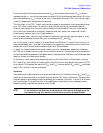
Because of the four-sampler receiver architecture of Option 400, additional correction of
the source match and load match terms is achieved by measuring the ratio of the two
“reference” receivers during the thru and line steps. These measurements characterize the
impedance of the switch and associated hardware in both the forward and reverse
measurement configurations. They are then used to modify the corresponding source and
load match terms (for both forward and reverse).
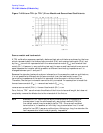
The Option 400 configuration with TRL established a higher performance calibration
method over TRL* when making in-fixture measurements, because all significant error
terms are systematically reduced. With TRL*, the source and load match terms are
essentially that of the raw, “uncorrected” performance of the hardware.
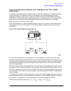
The TRL Calibration Procedure
Requirements for TRL Standards
When building a set of TRL standards for a microstrip or fixture environment, the
requirements for each of these standard types must be satisfied.
Types Requirements
THRU
(Zero length) • No loss. Characteristic impedance (Z
0
) need not be known.
•S
21
= S
12
= 1 ∠0°
•S
11
= S
22
= 0
THRU
(Non-zero
length) • Z
0
of the thru must be the same as the line. (If they are not the same,
the average impedance is used.)