


7-40
Operating Concepts
Measurement Calibration
Load Match
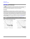
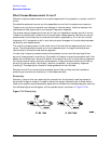
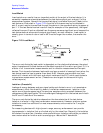
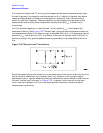
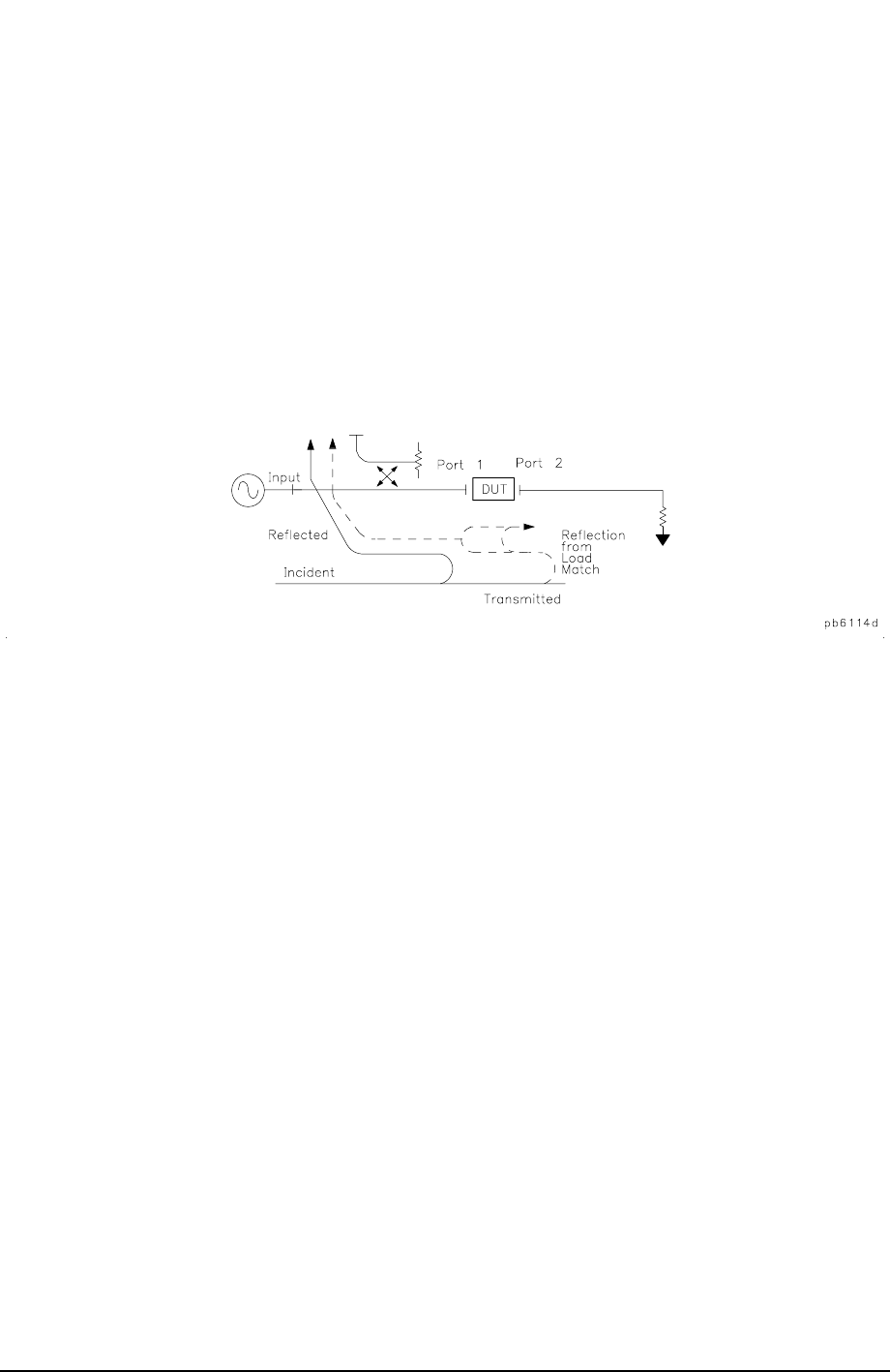
Load match error results from an imperfect match at the output of the test device. It is
caused by impedance mismatches between the test device output port and port 2 of the
measurement system. Some of the transmitted signal is reflected from port 2 back to the
test device as illustrated in Figure 7-23. A portion of this wave may be re-reflected to
port 2, or part may be transmitted through the device in the reverse direction to appear at
port 1. If the test device has low insertion loss (for example a filter pass band), the signal
reflected from port 2 and re-reflected from the source causes a significant error because the
test device does not attenuate the signal significantly on each reflection. Load match is
usually given in terms of return loss in dB: thus the larger the number, the smaller the
error.
Figure 7-23 Load Match
The error contributed by load match is dependent on the relationship between the actual
output impedance of the test device and the effective match of the return port (port 2). It is
a factor in all transmission measurements and in reflection measurements of two-port
devices. The interaction between load match and source match is less significant when the
test device insertion loss is greater than about 6 dB. However, source match and load
match still interact with the input and output matches of the DUT, which contributes to
transmission measurement errors. (These errors are largest for devices with highly
reflective ports.)
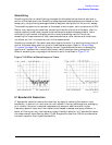
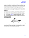
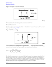
Isolation (Crosstalk)
Leakage of energy between analyzer signal paths contributes to error in a transmission
measurement, much like directivity does in a reflection measurement. Isolation is the
vector sum of signals appearing at the analyzer samplers due to crosstalk between the
reference and test signal paths. This includes signal leakage within the test set and in both
the RF and IF sections of the receiver.
The error contributed by isolation depends on the characteristics of the test device.
Isolation is a factor in high-loss transmission measurements. However, analyzer system
isolation is more than sufficient for most measurements, and correction for it may be
unnecessary.
For measuring devices with high dynamic range, accuracy enhancement can provide
improvements in isolation that are limited only by the noise floor. Generally, the isolation
falls below the noise floor, therefore, when performing an isolation calibration you should
use a noise reduction function such as averaging or reduce the IF bandwidth.