


3-6
Making Time Domain Measurements
Making Transmission Response Measurements
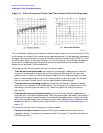
5. To transform the data from the frequency domain to the time domain and set the sweep
from 0 s to 6 µs, press:
The other time domain modes, low pass step and low pass impulse, are described in
"Time Domain Low Pass Mode" on page 3-15.
6. To better view the measurement trace, press:
and turn the front panel knob, or enter a value from
the front panel keypad.
7. To measure the peak response from the main path, press:
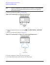
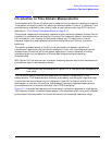
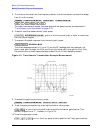
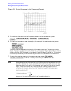
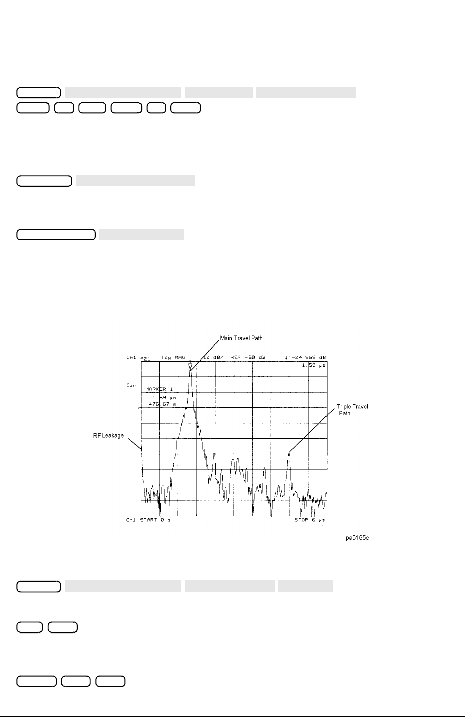
The three responses shown in Figure 3-3 are the RF leakage near zero seconds, the
main travel path through the filter, and the triple travel path through the filter. Only
the combination of these responses was evident to you in the frequency domain.
Figure 3-3 Time Domain Transmission Example Measurement
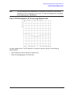
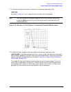
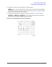
8. To access the gate function menu, press:
9. To set the gate parameters, by entering the marker value, press:
, or turn the front panel knob to position the center gate marker. This
marker, shaped like a “T”, is shown in Figure 3-4.
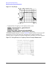
10.To set the gate span, press:
or turn the front panel knob to position the "flag" gate markers.
System
TRANSFORM MENU
BANDPASS
TRANSFORM ON
Start 0 G/n Stop 6 M/µ
Scale Ref
REFERENCE VALUE
Marker Search
SEARCH: MAX
System
TRANSFORM MENU
SPECIFY GATE
CENTER
1.6 M/µ
Span 1.2 M/µ