


7-48
Operating Concepts
Measurement Calibration
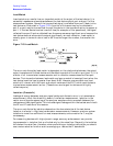
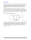
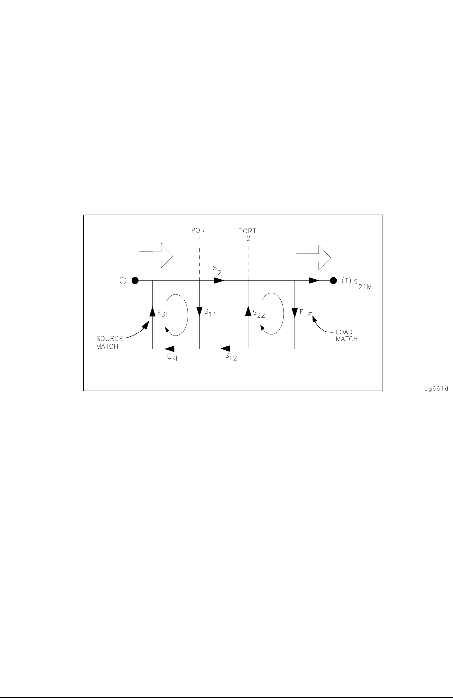
As in the reflection model, source match can cause the incident signal to vary as a function
of test device S
11A
. Also, since the test setup transmission return port is never exactly the
characteristic impedance, some of the transmitted signal is reflected from the test set
port 2, and from other mismatches between the test device output and the receiver input,
to return to the test device. A portion of this signal may be re-reflected at port 2, thus
affecting S
21M
, or part may be transmitted through the device in the reverse direction to
appear at port 1, thus affecting S
11M
. This error term, which causes the magnitude and
phase of the transmitted signal to vary as a function of S
22A
, is called load match, E
LF
. See
Figure 7-36.
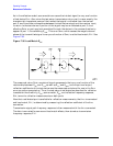
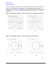
Figure 7-36 Load Match E
LF
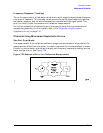
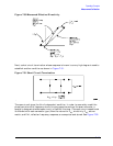
The measured value, S
21M
, consists of signal components that vary as a function of the
relationship between E
SF
and S
11A
as well as E
LF
and S
22A
, so the input and output
reflection coefficients of the test device must be measured and stored for use in the S
21A
error-correction computation. Thus, the test setup is calibrated as described for reflection
to establish the directivity, E
DF
, source match, E
SF
, and reflection frequency response,
E
RF
, terms for reflection measurements on both ports.
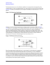
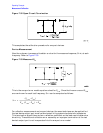
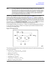
Now that a calibrated port is available for reflection measurements, the thru is connected
and load match, E
LF
, is determined by measuring the reflection coefficient of the thru
connection.
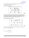
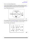
Transmission signal path frequency response is then measured with the thru connected.
The data is corrected for source and load match effects, then stored as transmission
frequency response, E
TF
.