


7-46
Operating Concepts
Measurement Calibration
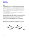
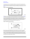
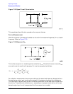
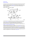
Figure 7-32 Open Circuit Termination
This completes the calibration procedure for one port devices.
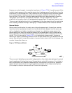
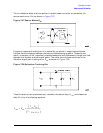
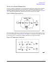
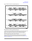
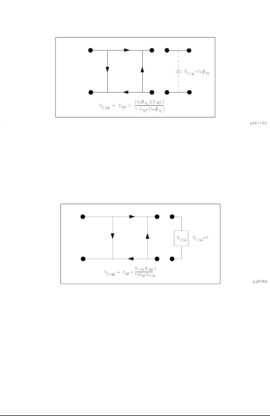
Device Measurement
Now the unknown is measured to obtain a value for the measured response, S
11M
, at each
frequency. Refer to Figure 7-33.
Figure 7-33 Measured S
11
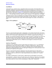
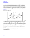
This is the one-port error model equation solved for S
11A
. Since the three errors and S
11M
are now known for each test frequency, S
11A
can be computed as follows:
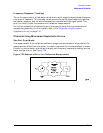
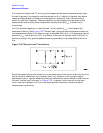
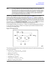
For reflection measurements on two-port devices, the same technique can be applied, but
the test device output port must be terminated in the system characteristic impedance.
This termination should have as low a reflection coefficient as the load used to determine
directivity. The additional reflection error caused by an improper termination at the test
device’s output port is not incorporated into the one-port error model.
S
11A
S
11M
E
DF
–()
E
SF
S
11M
E
DF
–()
E
RF
+
-----------------------------------------------------------------=