


7-73
Operating Concepts
TRL*/LRM* Calibration (ES Models Only)
• Attenuation of the thru need not be known.
• If the thru is used to set the reference plane, the insertion phase or
electrical length must be well-known and specified. If a non-zero length
thru is specified to have zero delay, the reference plane is established in
the middle of the thru, resulting in phase errors during measurement of
devices.
REFLECT • Reflection coefficient Γ magnitude is optimally 1.0, but need not be
known.
• Phase of Γ must known and specified to within ± 1/4 wavelength or
± 90°. During computation of the error model, the root choice in the
solution of a quadratic equation is based on the reflection data. An error
in definition would show up as a 180° error in the measured phase.
• Γ must be identical on both ports.
• If the reflect is used to set the reference plane, the phase response must
be well-known and specified.
LINE/MATCH
(LINE) • Z
0
of the line establishes the reference impedance of the measurement
(i.e. S
11
= S
22
= 0). The calibration impedance is defined to be the same
as Z
0
of the line. If the Z
0
is known but not the desired value (i.e., not
equal to 50 Ω), the SYSTEMS Z
0
selection under the TRL/LRM options
menu is used.
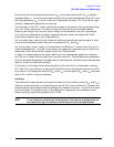
• Insertion phase of the line must not be the same as the thru (zero
length or non-zero length). The difference between the thru and line
must be between (20° and 160°) ± n x 180°. Measurement uncertainty
will increase significantly when the insertion phase nears 0 or an
integer multiple of 180°.
• Optimal line length is 1/4 wavelength or 90° of insertion phase relative
to the thru at the middle of the desired frequency span.
• Usable bandwidth for a single thru/line pair is 8:1 (frequency span:start
frequency).
• Multiple thru/line pairs (Z
0
assumed identical) can be used to extend
the bandwidth to the extent transmission lines are available.
• Attenuation of the line need not be known.
• Insertion phase must be known and specified within ± 1/4 wavelength
or ± 90°.
LINE/MATCH
(MATCH) • Z
0
of the match establishes the reference impedance of the
measurement.
• Γ must be identical on both ports.