


3-33
Making Time Domain Measurements
Resolution
For example, a cable with a teflon dielectric (0.7 relative velocity factor), measured under
the conditions stated above, has a fault location measurement response resolution of 0.45
centimeters. This is the maximum fault location response resolution. Factors such as
reduced frequency span, greater frequency domain data windowing, and a large
discontinuity shadowing the response of a smaller discontinuity, all act to degrade the
effective response resolution.
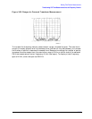
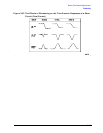
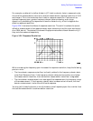
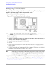
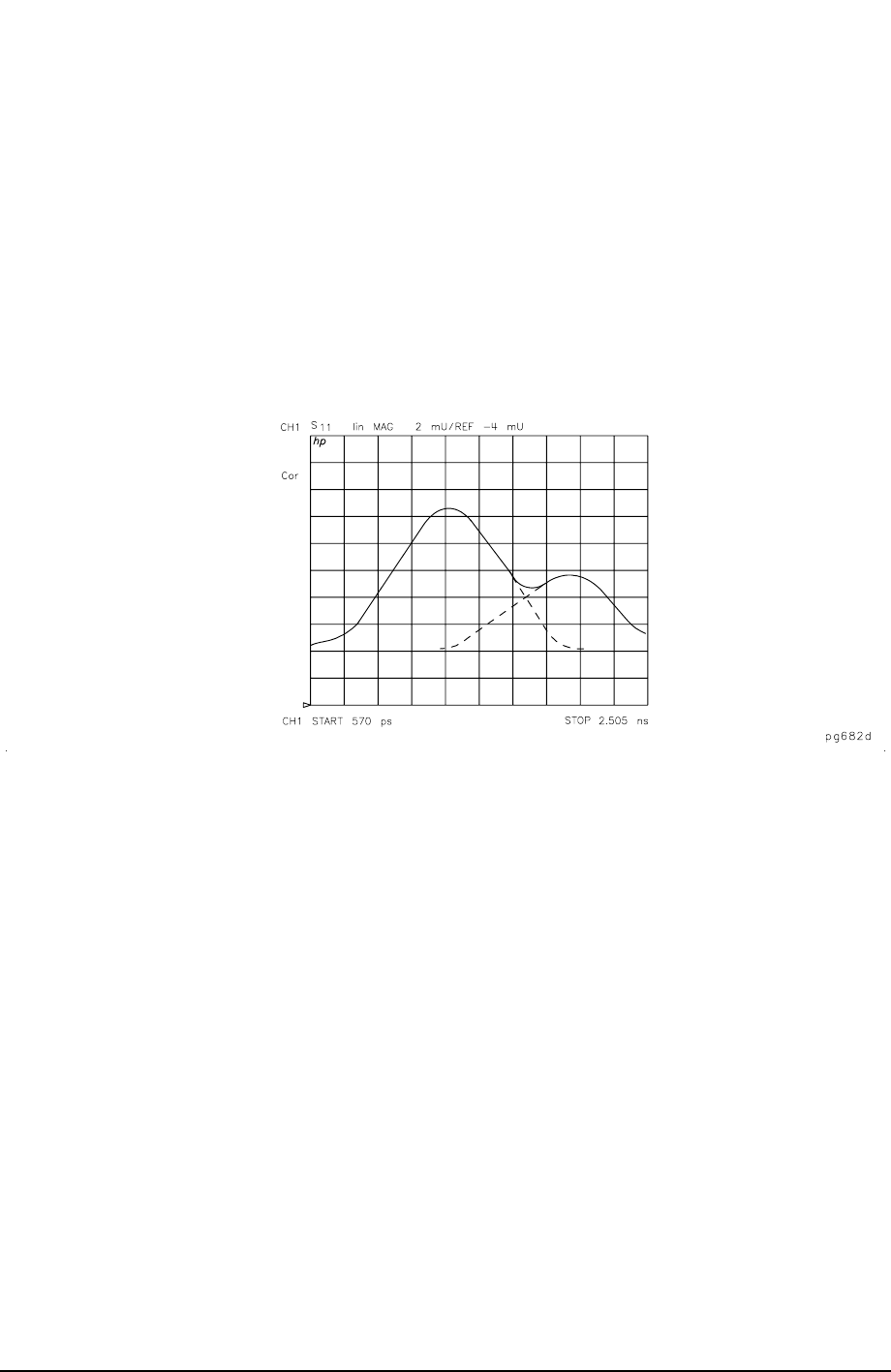
Figure 3-24 illustrates the effects of response resolution. The solid line shows the actual
reflection measurement of two approximately equal discontinuities (the input and output
of an SMA barrel). The dashed line shows the approximate effect of each discontinuity, if
they could be measured separately.
Figure 3-24 Response Resolution
While increasing the frequency span increases the response resolution, keep the following
points in mind:
• The time domain response noise floor is directly related to the frequency domain data
noise floor. Because of this, if the frequency domain data points are taken at or below
the measurement noise floor, the time domain measurement noise floor is degraded.
• The time domain measurement is an average of the response over the frequency range
of the measurement. If the frequency domain data is measured out-of-band, the time
domain measurement is also the out-of-band response.
You may (with these limitations in mind) choose to use a frequency span that is wider than
the test device bandwidth to achieve better resolution.