


1-63
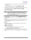
Making Measurements
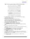
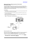
Measuring Amplifiers
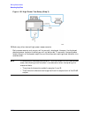
With the previous points in mind, the amount of attenuation can be calculated from the
following equations:
• Attenuator A = +20 dBm − 13 dB − (−10 dBm). Attenuator A = +17 dB
• Attenuator B = +30 dBm − 13 dB − (−10 dBm). Attenuator B = +27 dB
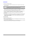
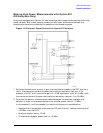
18.Set the internal step attenuators to the values calculated in the previous step (rounding
off to the highest 5 dB step). Press
.
19.Switch on the booster amplifier.
CAUTION From this point forward, DO NOT press unless you have first
switched off the booster amplifier or saved this state and renamed it to
UPRESET. Pressing will return the analyzer to its default power
level and default internal attenuator settings. This increase in power may
result in damage to the DUT or analyzer.
20.To activate the external reference mode, press
.
21.Measure the output power from test port 1 using a power meter and verify that it is as
expected.
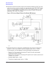
22.If you are measuring a highly reflective device, high power isolators should be inserted
in place of the jumpers located between the two sets of front panel SWITCH and
COUPLER connectors.
Final Setup
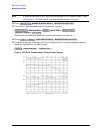
23.Confirm that all power and attenuator settings are correct, and set the following
measurement parameters:
24.Perform a response calibration:
• Connect the test port cables of the analyzer to form a thru configuration.
• Press .
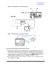
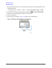
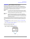
25.Make the connections as shown in Figure 1-51. Switch on the DUT and measure the S
21
gain of the amplifier under test to confirm the proper operation of the measurement test
setup.
Power
ATTENUATOR A
15 x1
ATTENUATOR B
25 x1
Preset
Preset
System
INSTRUMENT MODE
MDE
EXT R CHAN ON
Meas
Trans: FWD S21 (B/R)
Cal
CALIBRATE MENU
RESPONSE
THRU