


2-35
Making Mixer Measurements (Option 089 Only)
Phase or Group Delay Measurements
Phase or Group Delay Measurements
For information on group delay principles, refer to "Setting the Electrical Delay" on page
1-37.
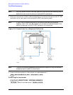
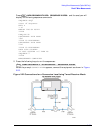
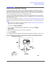
Phase Measurements
When you are making linear measurements, you must provide a reference for determining
phase by splitting the RF source power and send part of the signal into the reference
channel. (This does not work for frequency offset measurements, since the source and
receiver are functioning at different frequencies.)
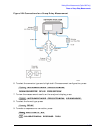
To provide a reference signal for the phase measurement, you need a second mixer. This
mixer is driven by the same RF and LO signals that are used to drive the mixer under test.
The IF output from the reference mixer is applied to the reference (R) channel of the
analyzer.
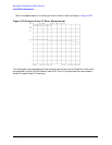
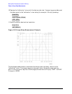
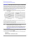
Phase Linearity and Group Delay
Group delay is the rate of change of phase through a device with respect to frequency
(dφ/dω). Traditionally, group delay has been used to describe the propagation delay (τ
g
),
and deviation from linear phase through a linear device. However, this parameter also
contains valuable information about transmission delay and distortion through a
non-linear device such as a mixer or frequency converter. For example, flat group delay
corresponds to low modulation distortion (that is, carrier and sidebands propagate at the
same rate).
Phase linearity and group delay are both measurements of the distortion of a transmitted
signal. Both measure the non-linearity of a device’s phase response with respect to
frequency.
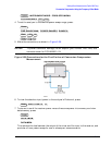
In standard vector error-correction, a thru (delay=0) is used as a calibration standard. The
solution to this problem is to use a calibration mixer with very small group delay as the
calibration standard.