


2-25
Making Mixer Measurements (Option 089 Only)
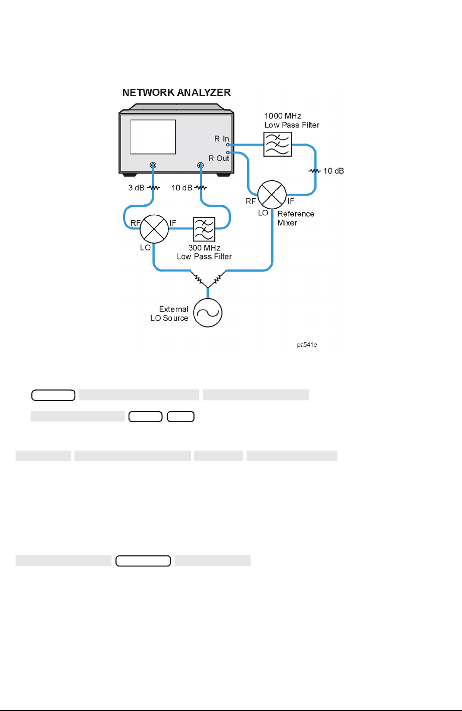
High Dynamic Range Swept RF/IF Conversion Loss
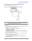
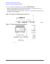
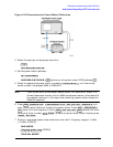
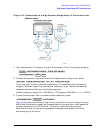
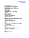
Figure 2-19 Connections for a High Dynamic Range Swept IF Conversion Loss
Measurement
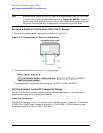
4. Set the analyzers LO frequency to match the frequency of the LO source by pressing:
5. To select the converter type and low-side LO measurement configuration, press:
In this low-side LO, down converter measurement, the analyzer’s source frequency
range will be offset higher than the receiver frequency range. The source frequency
range can be determined from the following equation:
receiver frequency range (100 – 1000 MHz) + LO frequency (1500 MHz) = 1.6 − 2.5 GHz
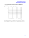
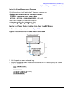
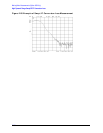
6. To view the conversion loss in the best vertical resolution, press:
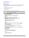
Figure 2-20 shows the conversion loss of this low-side LO mixer with output filtering.
Notice that the dynamic range from the pass band to the noise floor is well above the
dynamic range limit of the R Channel. If the mixer under test also contained
amplification, then this dynamic range would have been even greater due to the
conversion gain of the mixer.
System
INSTRUMENT MODE
FREQ OFFS MENU
LO FREQUENCY
1500 M/µ
RETURN
DOWN CONVERTER
RF > LO
FREQ OFFS ON
VIEW MEASURE
Scale Ref
AUTOSCALE