


2-21
Making Mixer Measurements (Option 089 Only)
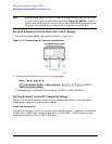
High Dynamic Range Swept RF/IF Conversion Loss
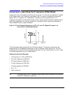
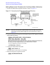
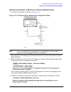
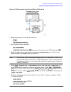
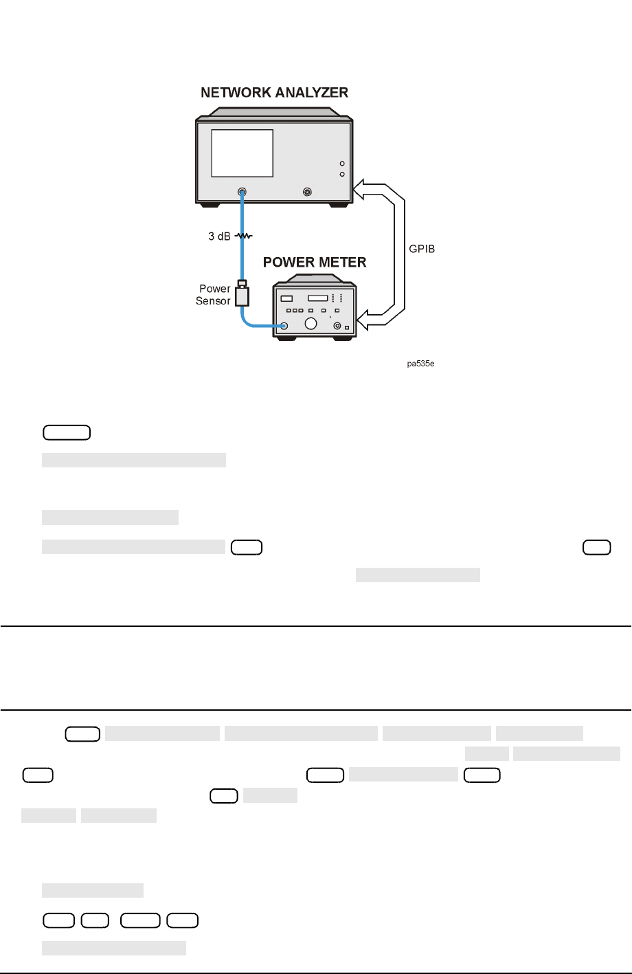
Figure 2-16 Connections for Power Meter Calibration
3. Select the analyzer as the system controller:
4. Set the power meter’s address:
(where aa is the power meter GPIB address)
5. Select the appropriate power meter by pressing until the correct
model number is displayed (436A or 438A/437).
NOTE The E4418B and E4419B power meters have a “437 emulation” mode. This
allows these power meters, with an 848X-series power sensor, to be used with
the network analyzer. In this step, when selecting a power meter, choose the
438A/437 selection.
6. Press and
enter the correction factors as listed on the power sensor. Press
(where fff is the frequency in MHz) (where nnn is the
calibration factor number) for each correction factor. When finished, press
.
7. Perform a one sweep power meter calibration over the IF frequency range at −5 dBm
(−10 dBm, 8722ES):
( , 8722ES)
Local
SYSTEM CONTROLLER
SET ADDRESSES
ADDRESS: P MTR/GPIB
aa
x1
POWER MTR [ ]
Cal
PWRMTR CAL
LOSS/SENSR LISTS
CAL FACTOR
SENSOR A
ADD
FREQUENCY
fff
M/µ
CAL FACTOR
nnn
x1
DONE
DONE
RETURN
ONE SWEEP
−5 x1 −10 x1
TAKE CAL SWEEP