


6-16
Calibrating for Increased Measurement Accuracy
Frequency Response Error Corrections
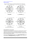
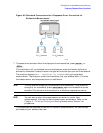
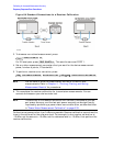
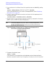
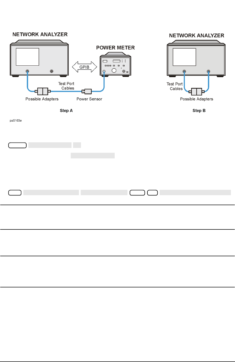
Figure 6-4 Standard Connections for a Receiver Calibration
3. To choose a non-ratioed measurement, press:
For ES analyzers, press . This sets the source at PORT 1.
4. Set any other measurement parameters that you want for the device measurement:
power, number of points, IF bandwidth.
5. To perform a receiver error correction, press:
NOTE You can save or store the measurement correction to use for later
measurements. Refer to Chapter 4 , “Printing, Plotting, and Saving
Measurement Results” for procedures.
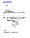
6. This completes the receiver calibration for transmission measurements. You can
connect and measure your device under test.
NOTE The accuracy of the receiver calibration will be nearly the same as the test
port power accuracy; and the test port power accuracy can be significantly
improved by performing a power meter source calibration, as described later
in "Power Meter Measurement Calibration" on page 6-33.
Calibrations at powers other than 0 dBm are possible. Receiver calibration normalizes the
trace to the value set for the reference level. For example, to do a receiver calibration at
−10 dBm, set the source to −10 dBm, set the reference level to −10 dBm, then perform the
receiver calibration.
Meas
INPUT PORTS
B
TEST PORTS 1
Cal
CALIBRATE MENU
RECEIVER CAL
−10 x1
TAKE RCVR CAL SWEEP