


1-62
Making Measurements
Measuring Amplifiers
16.Estimate the maximum amount of gain that could be provided by the DUT and, as a
result, the maximum amount of power that could be received by TEST PORT 2 when
the DUT is in compression. For example, if a DUT with a maximum gain of +10 dB
receives an input of +20 dBm, then the maximum amount of power that could be
received by TEST PORT 2 is +30 dBm.
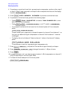
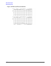
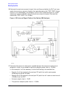
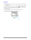
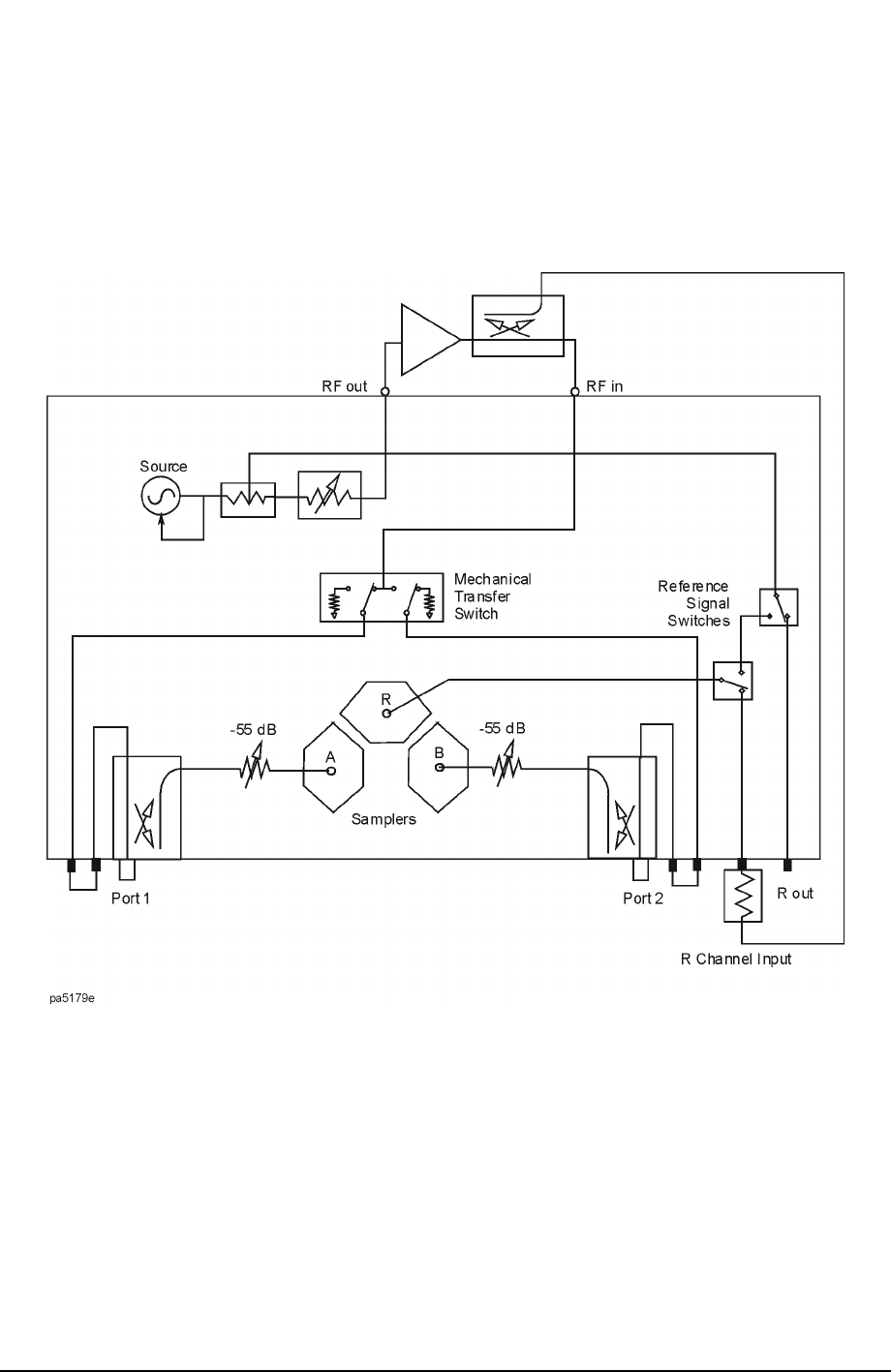
Figure 1-50 Internal Signal Paths of the Option 085 Analyzer
17.Calculate the amount of attenuation needed between the analyzer’s couplers and
samplers in order to not exceed the optimum sampler power level of −10 dBm.
In this example, it will be necessary to take the following into consideration:
• Sampler A will be coupled to the analyzer RF path that could receive power
reflections as high as +20 dBm.
• Sampler B will be coupled to the analyzer RF path that will receive a maximum of
+30 dBm from the DUT.
• Analyzer coupler loss is −13 dB.
• The optimum sampler power level is −10 dBm.