


7-42
Operating Concepts
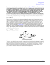
Measurement Calibration
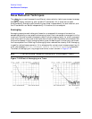
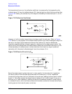
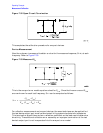
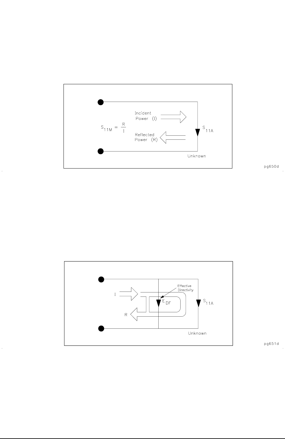
To characterize the errors, the reflection coefficient is measured by first separating the
incident signal (I) from the reflected signal (R), then taking the ratio of the two values. See
Figure 7-25. Ideally, (R) consists only of the signal reflected by the test device (S
11A
, for S
11
actual).
Figure 7-25 Reflection Coefficient
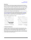
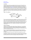
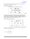
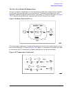
However, all of the incident signal does not always reach the unknown. Refer to Figure
7-26. Some of (I) may appear at the measurement system input due to leakage through the
test set or through a signal separation device. Also, some of (I) may be reflected by
imperfect adapters between a signal separation device and the measurement plane. The
vector sum of the leakage and the miscellaneous reflections is the effective directivity, E
DF
.
Understandably, the measurement is distorted when the directivity signal combines
vectorally with the actual reflected signal from the unknown, S
11A
.
Figure 7-26 Effective Directivity E
DF
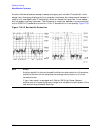
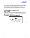
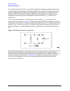
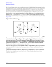
Since the measurement system test port is never exactly the characteristic impedance
(50 ohms), some of the reflected signal bounces off the test port, or other impedance
transitions further down the line, and back to the unknown, adding to the original incident
signal (I). This effect causes the magnitude and phase of the incident signal to vary as a
function of S
11A
and frequency. Leveling the source to produce a constant incident signal
(I) reduces this error, but since the source cannot be exactly leveled at the test device input,
leveling cannot eliminate all power variations.