


7-69
Operating Concepts
TRL*/LRM* Calibration (ES Models Only)
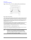
Also notice that the forward source match (E
SF
) and reverse load match (E
LR
) are both
represented by ε
11
, while the reverse source match (E
SR
) and forward load match (E
LF
) are
both represented by ε
22
. In order to solve for these eight unknown TRL error terms, eight
linearly independent equations are required.
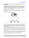
The first step in the TRL* 2-port calibration process is the same as the transmission step
for a Full 2-port calibration. For the thru step, the test ports are connected together
directly (zero length thru) or with a short length of transmission line (non- zero length
thru) and the transmission frequency response and port match are measured in both
directions by measuring all four S-parameters.
For the reflect step, identical high reflection coefficient standards (typically open or short
circuits) are connected to each test port and measured (S
11
and S
22
).
For the line step, a short length of transmission line (different in length from the thru) is
inserted between port 1 and port 2 and again the frequency response and port match are
measured in both directions by measuring all four S-parameters.
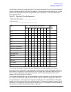
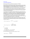
In total, ten measurements are made, resulting in ten independent equations. However,
the TRL error model has only eight error terms to solve for. The characteristic impedance
of the line standard becomes the measurement reference and, therefore, has to be assumed
ideal (or known and defined precisely).
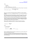
At this point, the forward and reverse directivity (E
DF
and E
DR
), transmission tracking
(E
TF
and E
TR
), and reflection tracking (E
RF
and E
RR
) terms may be derived from the TRL
error terms. This leaves the isolation (E
XF
and E
XR
), source match (E
SF
and E
SR
) and load
match (E
LF
and E
LR
) terms to discuss.
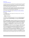
Isolation
Two additional measurements are required to solve for the isolation terms (E
XF
and E
XR
).
Isolation is characterized in the same manner as the Full 2-port calibration. Forward and
reverse isolation are measured as the leakage (or crosstalk) from port 1 to port 2 with each
port terminated. The isolation part of the calibration is generally only necessary when
measuring high loss devices (greater than 70 dB).
NOTE If an isolation calibration is performed, the fixture leakage must be
the same during the isolation calibration and the measurement.