


6-42
Calibrating for Increased Measurement Accuracy
Calibrating for Noninsertable Devices
Perform the 2-Port Error Corrections
1. Check the firmware to see if your revision supports adapter removal calibration by
pressing:
2. Determine the delay of adapter A3.
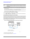
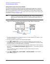
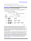
a. Refer to Figure 6-14 while performing the steps in this procedure. Also refer to
page 6-41 for an explanation of A1, A2, and A3.
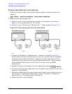
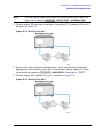
b. Perform a 1-port calibration at “Reference Port 1”. Refer to Step A of Figure 6-14.
Figure 6-14 Determining the Electrical Delay Setup
c. Connect the A3 adapter to "Reference Port 1" as shown in Step B of Figure 6-14.
Attach the short (from the calibration kit for port 2) to the other end of the adapter.
You must know the delay of the short. The delay of the short can be found in the
calibration kit that you are using. Typical delays of shorts are 31.7 ps for the short
from the 85052D calibration kit and 31.8 ps for the short from the 85033D
calibration kit.
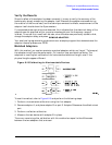
d. Measure the delay of the adapter and short together by pressing .
e. Divide the resulting delay measurement by 2 to determine the delay of the thru and
the short in one direction.
f. Subtract the offset delay of the short (determined in step c) from the delay of the thru
and the short in one direction (determined in step e). The result is the electrical
delay of the thru. This value is used in the Step 12.
g. Remove the short from the adapter.
Cal
MORE
ADAPTER REMOVAL
HELP ADAPT REMOVAL
Format
DELAY