


1-60
Making Measurements
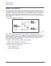
Measuring Amplifiers
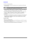
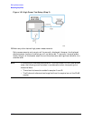
5. Switch on the booster amplifier.
6. Using a power meter, measure the output power from the coupled arm and the open
port of the coupler.
NOTE Depending on the power meter being used, additional attenuation may have
to be added between the coupler port and the power meter.
7. Verify the gain of the booster amplifier. For example, if the analyzer output power level
was set to −20 dBm and the output power measured from the open end of the coupler
was −5 dBm, then the gain of the booster amplifier would be +15 dB.
8. Verify that the power measured in the previous steps is well within acceptable limits
(less than −10 dBm for the coupled arm, less than +43 dBm for the open port).
9. Estimate the maximum power level that will be needed to force the DUT into
compression.
10.At the maximum estimated power level, determine if the maximum output power from
the coupled arm of the coupler will be higher than the acceptable limit. If so, add the
appropriate amount of attenuation that will keep the coupled output power below
−10 dBm and above −35 dBm.
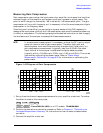
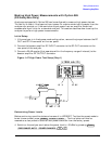
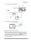
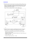
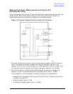
Additional Setup
11.Switch off the booster amplifier.
12.Make a connection between the open port of the 20 dB coupler and the RF IN connector
on the rear panel of the analyzer.
13.Make a connection between the coupled arm of the 20 dB coupler (along with any added
attenuation) and the R CHANNEL IN connector on the front panel.