


7-77
Operating Concepts
TRL*/LRM* Calibration (ES Models Only)
The location of the reference plane is determined by the selection of and
. By default, the reference plane is set with the thru standard which
must have a known insertion phase or electrical length. If a non-zero length thru is
specified to have zero delay, the reference plane will be established in the middle of the
thru. The reflect standard may be used to set the reference plane instead of the thru
provided the phase response (offset delay, reactance values and standard type) of the
reflect standard is known and is specified in the calibration kit definition.
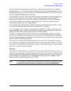
NOTE Dispersion Effects
Dispersion occurs when a transmission medium exhibits a variable
propagation or phase velocity as a function of frequency. The result of
dispersion is a non-linear phase shift versus frequency, which leads to a group
delay which is not constant. Fortunately, the TRL calibration technique
accounts for dispersive effects of the test fixture up to the calibration plane,
provided that:
1. The thru (zero or non-zero length) is defined as having zero electrical
length and is used to set the reference plane ( ).
2. The transmission lines used as calibration standards have identical
dispersion characteristics (i.e., identical height, width and relative
dielectric constant).
When a non-zero length thru is used to set the reference plane, it should be
defined as having zero length in the TRL standards definition, even though it
has physical length. The actual electrical length of the thru standard must
then be subtracted from the actual electrical length of each line standard in
the TRL calibration kit definition. The device must then be mounted between
two short lengths of transmission line so that each length is exactly one-half
of the length of the non-zero length thru standard. In this configuration, the
measurement will be properly calibrated up to the point of the device.
SET REF: THRU
SET REF: REFLECT
SET REF: THRU