


2-16
Making Mixer Measurements (Option 089 Only)
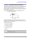
Conversion Loss Using the Frequency Offset Mode
5. To perform a one sweep power meter calibration over the RF frequency range at 0 dBm
(−10 dBm for 8722ES), press:
(or on 8722ES: )
NOTE Because power meter calibration requires a longer sweep time, you may want
to reduce the number of points before pressing . After the
power meter calibration is finished, return the number of points to its original
value and the analyzer will automatically interpolate this calibration.
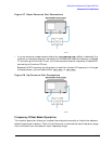
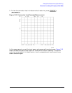
6. Make sure the power meter calibration is on. When the power meter calibration is on,
“PC” is displayed at the left edge of the display. Refer to Figure 2-15 on page 2-19 for an
example.
7. From the front panel of the analyzer, set the desired IF start and stop frequencies by
pressing:
Note that these are the example IF start and stop frequencies. Enter the IF
start and stop frequencies for your measurement instead.
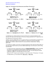
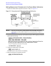
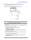
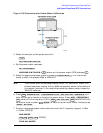
8. To calibrate the R channel over the IF range, connect the equipment as shown in Step 2
of Figure 2-11.
NOTE An error message will be displayed while the R In port is disconnected.
Ignore this error message until R In port is reconnected.
9. Press
.
❏ The low pass filter is required to limit the range of frequencies passed into the R
channel input port. The filter is selected to pass the IF frequencies for the
measurement but prevent the LO feedthrough and unwanted mixer products from
confusing the phase-lock loop operation.
❏ A pad is used to isolate the filter and improve the IF port match for the mixer.
Once completed, the display should read 0 dBm (−10 dBm for 8722ES).
10. Save the power meter and receiver calibration to an instrument state by pressing
.
Cal
PWRMTR CAL
ONE SWEEP
0 x1 −10 x1
TAKE CAL SWEEP
TAKE CAL SWEEP
System
INSTRUMENT MODE
FREQ OFFS MENU
Start
100
M/µ Stop
350
M/µ
Cal
CALIBRATE MENU
RECEIVER CAL
0 x1
TAKE RCVR CAL SWEEP
Save/Recall
SAVE STATE