6-12 SPARC Enterprise M8000/M9000 Servers Service Manual • October 2012
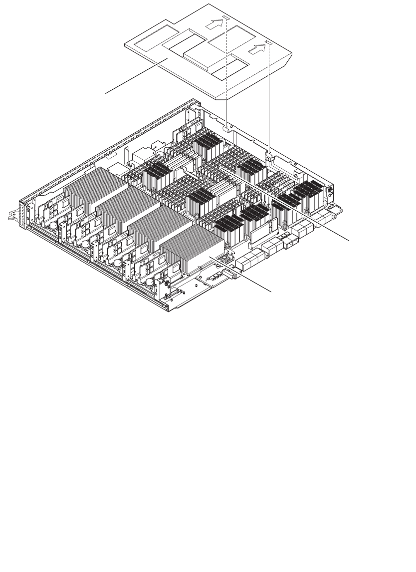
FIGURE 6-7 CPU Module and DIMM Locations
12. Place the DIMM duct cover back at its original location. Insert the L-shaped
projections on the CMU frame into the two positioning slits of the DIMM duct cover.
13. Follow the removal instructions in Step 9 in reverse order to attach the cover of the
CMU, and press the latch pins to lock the latches.
CPU module (x4)
DIMM (x32)
DIMM duct cover


