6-30 SPARC Enterprise M8000/M9000 Servers Service Manual • October 2012
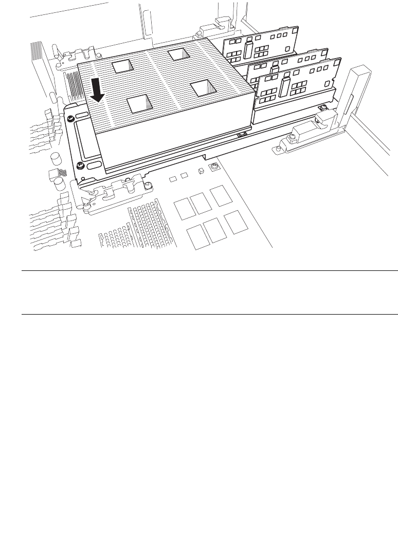
6. Fit the guide pin on the heat sink side of the CPU Module into the groove of the
CMU guide lock.
FIGURE 6-22 Set CPU Module on the Guide Lock (2)
Note – Each CPU Module has two guide pins and two CMU guide locks on the DDC side.
Perform the work in such a way that both guide pins and both guide locks are mounted
correctly.
7. Move the CPU Module back and forth to confirm that the pins are in the grooves.


