Chapter 20 Backplane Replacement 20-21
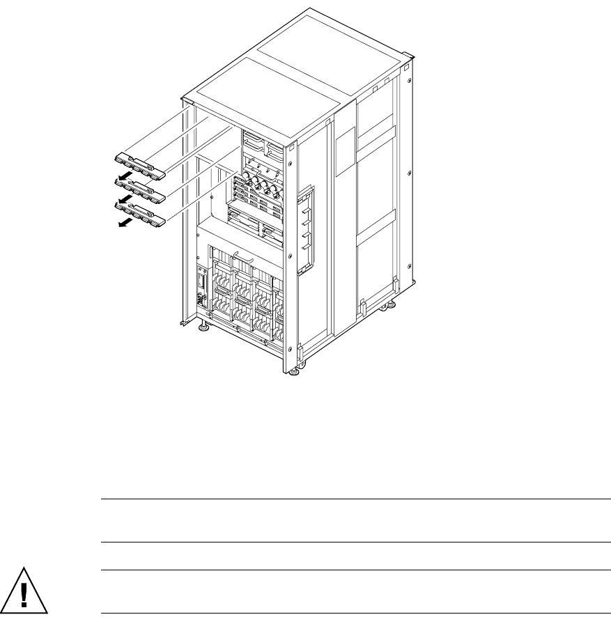
FIGURE 20-12 Removing the PSUBP (Front of the M9000)
10. Place the removed BP on an antistatic mat.
11. Mount the replacement BP by following the removal instructions in Step 8 and Step 9
in reverse order. Align the holes by the side of the thumb screws of the PSUBP with
the two guide pins in the cabinet.
Note – To mount a FAN BP on a fan shelf that has a guide pin, align the FAN BP with the
guide pin during mounting.
Caution – Be sure not to hit connector parts of the BP against anything. Otherwise, the
connection pins may be seriously damaged.
12. Switch on all main line switches for the AC section (ACS) in the power supply
system.
13. Confirm that the XSCF STANDBY LED (green) on the operator panel remains lit.
If it is blinking, wait until it remains lit.


