Chapter 6 Replacement of CPU/Memory Board Unit (CMU), CPU Module, and DIMM 6-25
6.4.2 CPU Module Replacement
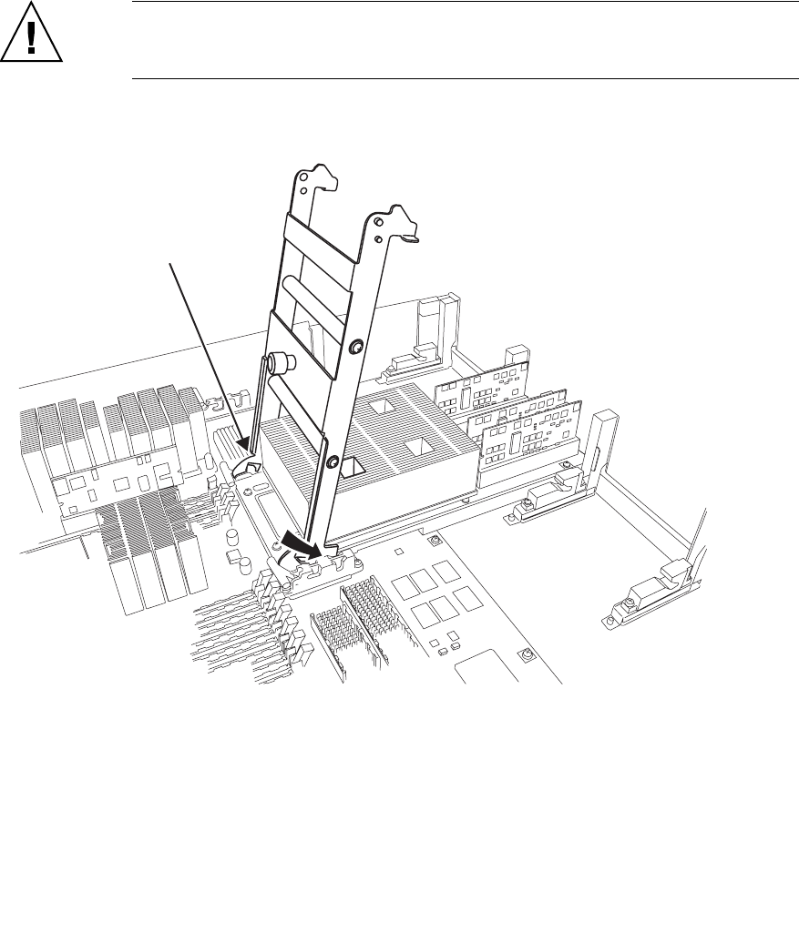
1. Insert the tips on the ejecting side of the CPU module insertion/extraction tool (B)
under the CPU module guide pins. Insert the shorter guide pin into the groove of the
guide lock of the CMU.
Caution – When using the CPU Module insertion/extraction tool, make sure that it is set in
position and used in the manner shown in the figure. If the CPU Module insertion/extraction
tool is set and used in a different direction from the figure, serious damage may result.
FIGURE 6-15 Set CPU Module Insertion/Extraction Tool
Ejecting side (B)
Injecting side (A)


