


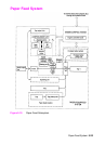

Paper Feed System 5-35
and by the six switches (SW600, 601, 602, 603, 604, 605) on the
Paper Size Detection PCA for the HP LaserJet 4000 T, 4000 TN,
4050 T, and 4050 TN.
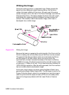
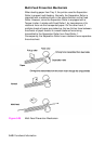
While the Main Motor rotates, the Tray 1 Pickup Solenoid (SL102) is
turned on, the Tray 1 Pickup Roller rotates, and a sheet of paper is fed
into the printer.
The paper passes the pre-feed roller, which compensates for the
skew of the paper.
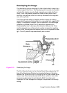
After the top of page sensor (PS103) detects the leading edge of the
paper, the horizontal synchronization signal (/TOP) is sent from the
Engine Controller Board to the Formatter.
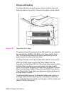
After the Formatter receives the /TOP signal, the /VDO signal is sent;
this synchronizes the leading edge of the image on the Drum with the
leading edge of the paper. The paper goes through transfer,
separation, and fusing stages, passes through the delivery unit, and
is delivered to the Top Output Bin or Rear Output Bin.
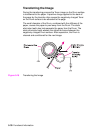
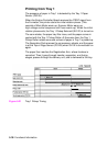
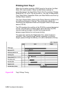
There are four photo-interrupters (PS102, PS103, PS106, PS501) in
the paper path that detect the presence of paper. If the paper does
not reach or pass these sensors within a prescribed time interval, the
microprocessor on the Engine Controller Board notifies the Formatter
of a paper jam.
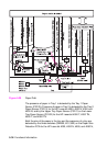
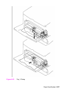
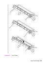
Clutches and Sensors
See “Reference Diagrams” starting on page 7-84 for locations of
switches, sensors, and clutches.