


Chapter 2.
NAMES AND FUNCTIONS OF PARTS
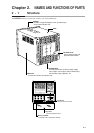
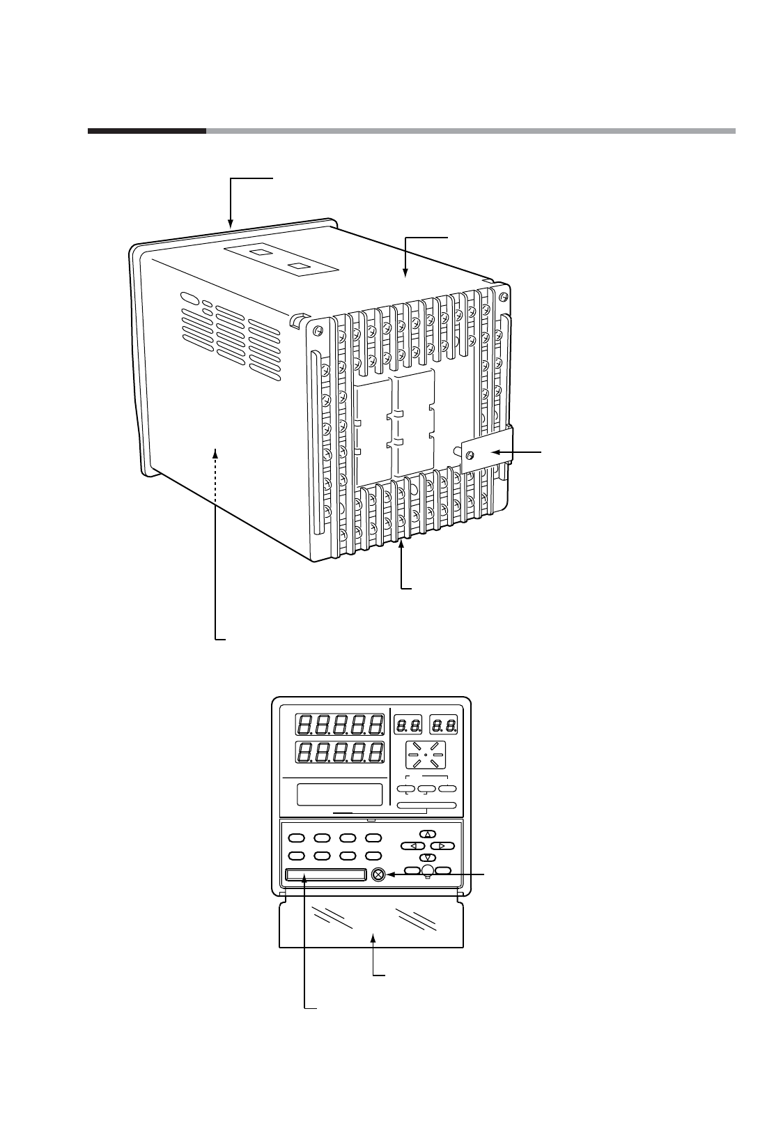
2 - 1 Structure
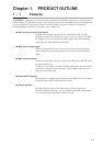
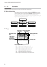
The DCP552 consists of a main unit, console, case, and terminal base.
2-1
Console
Provides 7-segment displays, LEDs, operation keys,
and a loader interface unit.
Terminal base
Provides terminals to connect a power supply,
input, output, event output, external switch input,
and auxiliary output (optional) , etc.
Case
Main unit
Console and electric circuit board, etc.
Terminal cover
Covers power supply and
prevents electric shock.
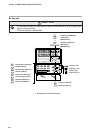
FUNC AT SETUP ENTER
A/M PID PARA CLR
CARD
LOAD SAVE
LOADER
CYC
OUT
DEV
PV
SP
TM
SYN
RUN
HLD
MAN
PRG
AT
BAT
EG1
EG2
PROG RUN/HOLD DISP
RESET
PROG SEG
PROFILE
MESSAGE
MESSAGE
ADV
Lock screw
Secures case to main unit.
Key cover
Prevents operation errors.
Memory card slot
A memory card is inserted into this slot.