


12-11
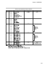
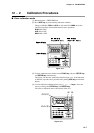
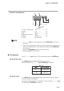
● Built-in clock adjustment
Figure 12-4.
Example:
A: 2 digits of calendar year 1993 ……………………93
B: Month April ……………………04
C: Day 5th day …………………05
D: Hour (24 hour system) 3PM ……………………15
E: Minute 6 minutes ………………06
F: Second Not changeable
NOTE
1. ↑, ↓, ←, →, keys are used to change the values, and ENTER key is used to store
the values.
2. Clock is still progressing the operation even after the calibration step is moved to this
built-in clock adjustment item. After entering the changing mode by ENTER key,
the clock stops.
3. After pressing ENTER key, the clock starts from 0 second.
4. Writing to EEPROM is not necessary.
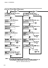
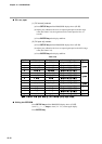
■ PV calibration
Scroll ↑, ↓, ←, →, keys to show (1011) on upper display, then press ENTER key.
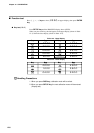
● Input CH No. select
Press SETUP key until the PROG/SEG display shows (01-01).
Input the channel No. by ↑, ↓, ←, →, keys ( ENTER key not required).
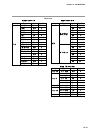
Table 12-8.
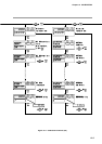
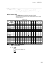
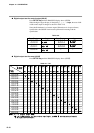
● Gain No. select
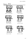
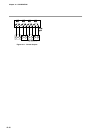
Press SETUP key until the PROG/SEG display shows (01-02). Connect calibration
device (See Section “12-3 Set Up”).
Input the gain number (See Table 12-9 and Table 12-10) by scrolling ↑, ↓, ←, →, keys
the upper display ( ENTER key not required).
00 0 0 0
0 0 0 0 1
Chapter 12. CALIBRATION