


4-14
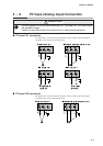
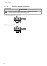
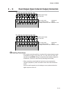
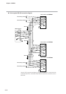
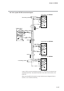
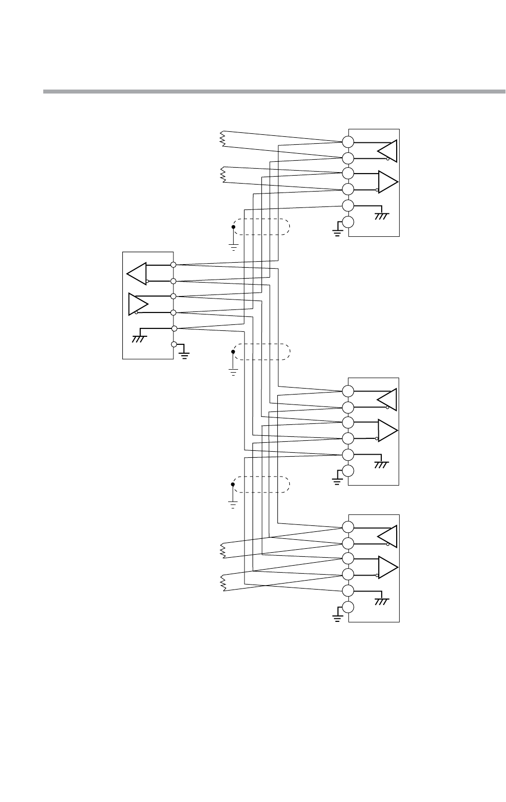
● 5-wire system RS-485 connection diagram
Attach 1/2W or greater terminating resistances of 150Ω ±5% at each end of the
communications lines. Ground the shield FGs at one end in one location, not at
both ends.
SDA
SDB
RDA
RDB
SG
FG
SDA
Shield
SDB
RDA
RDB
SG
Shield
Shield
Master station
Terminating resistor
Terminating resistor
Terminating resistor
Terminating resistor
Slave station side DCP552
SDA
SDB
RDA
RDB
SG
RDA
RDB
SDA
SDB
SG
FG
Slave station side DCP552
Slave station side DCP552
60
61
62
63
64
60
61
62
63
64
60
61
62
63
64
FG
FG
Chapter 4. WIRING