


6-17
Chapter 6. OPERATION
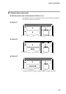
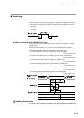
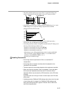
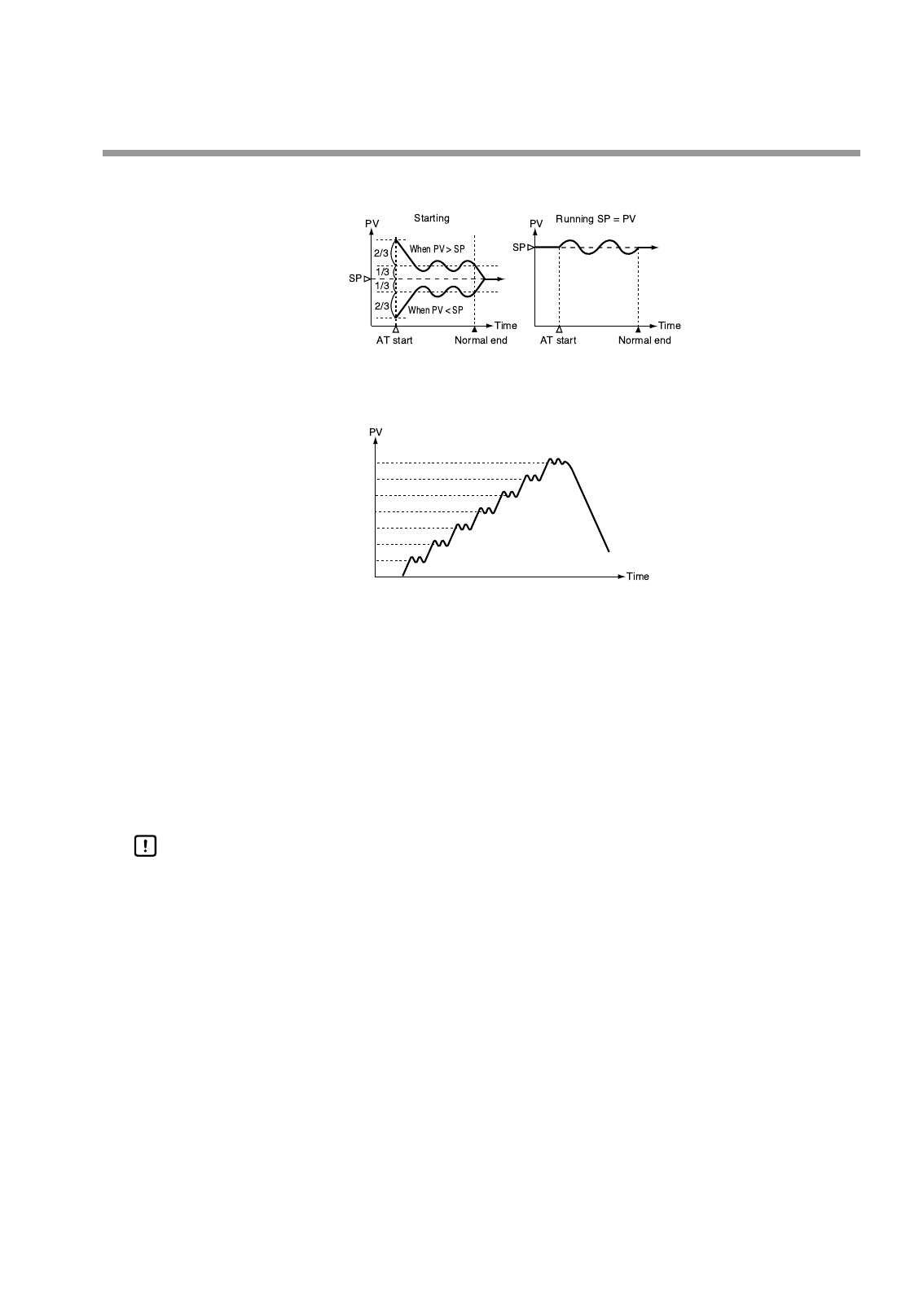
• The point at which output reverses (lower limit ⇔ upper limit) during auto-
tuning is determined from the SP and PV values at AT startup as follows.
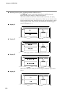
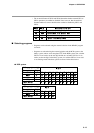
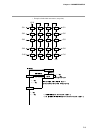
• Auto-tuning performed using a variable parameter PA08 setting of 3 or 4 and a
PA93 setting of 3 or 4 cause auto-tuning to be performed on SP, PID
parameters tP-A1 to tP-A7, in order.
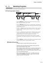
• Auto-tuning can be started by the AT key, external switch input and by
transmission. The AT LED flashes during auto-tuning.
• Auto-tuning terminates without writing PID constants and the AT LED goes off
when any of the following conditions occur.
• Operation is terminated by pressing of the AT key.
• Operation is terminated by an external switch input.
• Operation is terminated by transmission.
• Mode change occurs. (When the MANUAL mode is invoked; the READY
mode is invoked by setting PA08 and PA93 to 1 or 2, the RUN mode is
invoked by setting PA08 and PA93 to 3 or 4.)
• When PV goes outside the range.
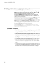
Handling Precautions
• Auto-tuning cannot be performed in CH2 on a model with CP
compensation.
• Auto-tuning does not operate normally when the equipment to be
controlled is not connected.
• The time required for auto-tuning depends on the equipment controlled.
• When auto-tuning is executed, control is terminated , lower and higher
limit outputs are repeated several times and PV fluctuates. When
equipment failure may be caused by PID fluctuations, set the PID value
manually.
If just PID value can not be got in case of control object, sets PID value
with manual.
• Variable parameter PA08 and PA93 settings make values set at the start
of auto-tuning valid. A change in the PA08 and PA93 settings made
during auto-tuning execution is ignored. The new value is valid in the
next auto-tuning operation.
tP-A7
tP-A6
tP-A5
tP-A4
tP-A3
tP-A2
tP-A1