


10-2
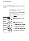
■ Alarm code display
The DCP552 is designed to alternate display of the following alarm codes and
normal display items in one-second intervals on display panel 1 when input
failures or instrument system failures are detected.
In cases of multiple alarm codes, display of the codes is alternated with normal
display items, starting in order from the alarm code with the smallest number.
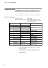
■ Alarm classification
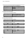
PV range alarm group : AL01 to AL04
Measuring instrument alarm group : AL90 to AL99, and battery voltage drop
(In case of battery voltage drop, BAT LED
of the console is flickered.)
*1: When AL90 is generated, the alarm code stays on and continued
operation is disabled.
*2:Data checks performed by AL93 and AL97 may fail to detect
corrupted data. When this happens, the alarm can be turned off by
entering normal data.
Chapter 10. TROUBLESHOOTING
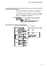
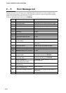
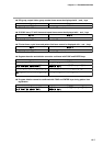
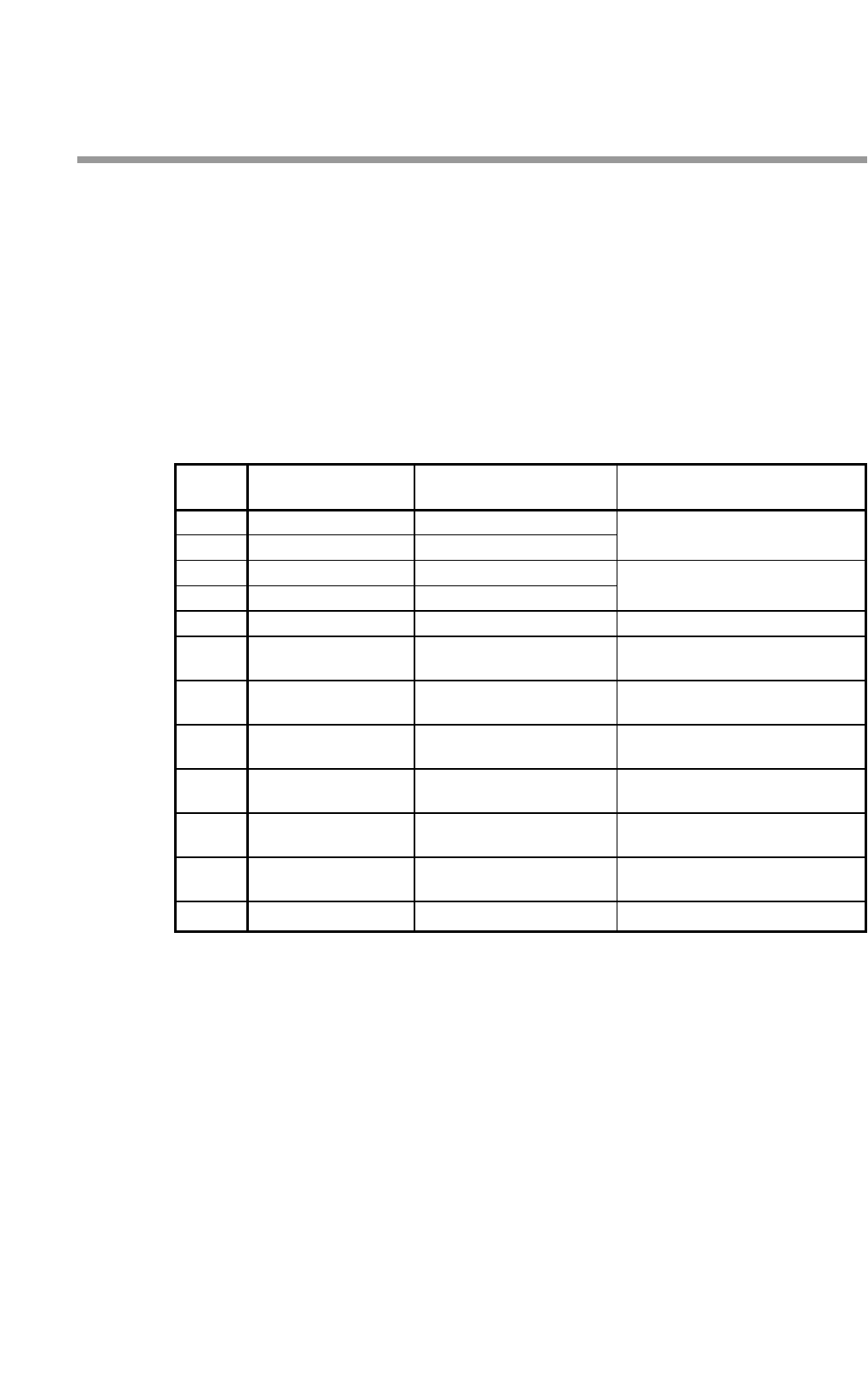
Alarm Alarm name Contents Countermeasure
code
AL01 PV1 overrange
PV1 is more than 110%FS.
Check PV1.
AL02 PV1 underrange PV1 is less than –10%FS.
AL03 PV2 overrange
PV2 is more than 110%FS.
Check PV2
AL04 PV2 underrange PV2 is less than –10%FS.
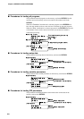
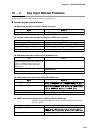
AL90
Board configuration failure
Incorrect board configuration
Request the repair.
AL92
Adjustment value is abnormal.
Analog input/output Request the repair.
adjustment data were broken.
AL93
Setup data is abnormal.
Setup data were broken. Check the setup data, and reset
the data.
AL94
Variable parameter is abnormal.
Variable parameter were Check the variable parameter,
broken. and reset the data.
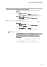
AL95
PID parameter is abnormal.
PID parameter were
broken
.
Check the PID parameter,
(Fixed command control data is abnormal.)
and reset the data.
AL96
Program data is abnormal.
Program data were
broken
.
Check the program data,
and reset the data.
AL97
Event configuration data
Event configuration data
Check the event configuration data,
is abnormal. were broken. and reset the data.
AL99 PROM is abnormal.
System program were corrupted.
Request the repair.