2 - 2 Console
2-2
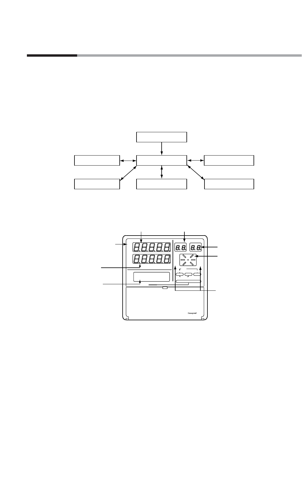
The console consists of the operation keys, displays and LEDs (light emitting diodes).
■ Basic display status
Basic display status shows the running condition of the DCP552 on the console.
The basic display status is invoked when the DCP552 is powered up (power on).
Key operations make it possible to change from the basic display status to
parameter setting status, program setting status, program copy status, memory card
operation status and general reset status.
Key operations can also be used to return to the basic display status.
■ Display
● Basic display LEDs
PV : Lights during PV display, otherwise off.
DEV : Lights during deviation display, otherwise off.
OUT : Lights during output display, otherwise off.
CYC : Lights during cycle display, otherwise off.
SP : Lights during SP display, otherwise off.
TM : Lights during time display, otherwise off.
SYN : Lights in CH1 and CH2 sync mode, otherwise off.
Chapter 2. NAMES AND FUNCTIONS OF PARTS
Power on
Parameter setting status
Program setting status
Program copy status
Memory card operation status
General reset status
Basic display status
CYC
OUT
DEV
PV
SP
TM
SYN
RUN
HLD
MAN
PRG
AT
BAT
EG1
EG2
PROG RUN/HOLD DISP
RESET
PROG SEG
PROFILE
MESSAGE
MESSAGE
ADV
Display panel 1
(Upper display)
Program number display
(PROG display)
Segment number display
(SEG display)
Profile display
Mode display LED
Message display
LCD
(16 characters × 2 lines)
Display panel 2
(Lower display)
Basic display contents
LED


