


15
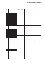
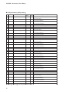
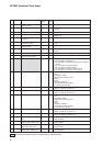
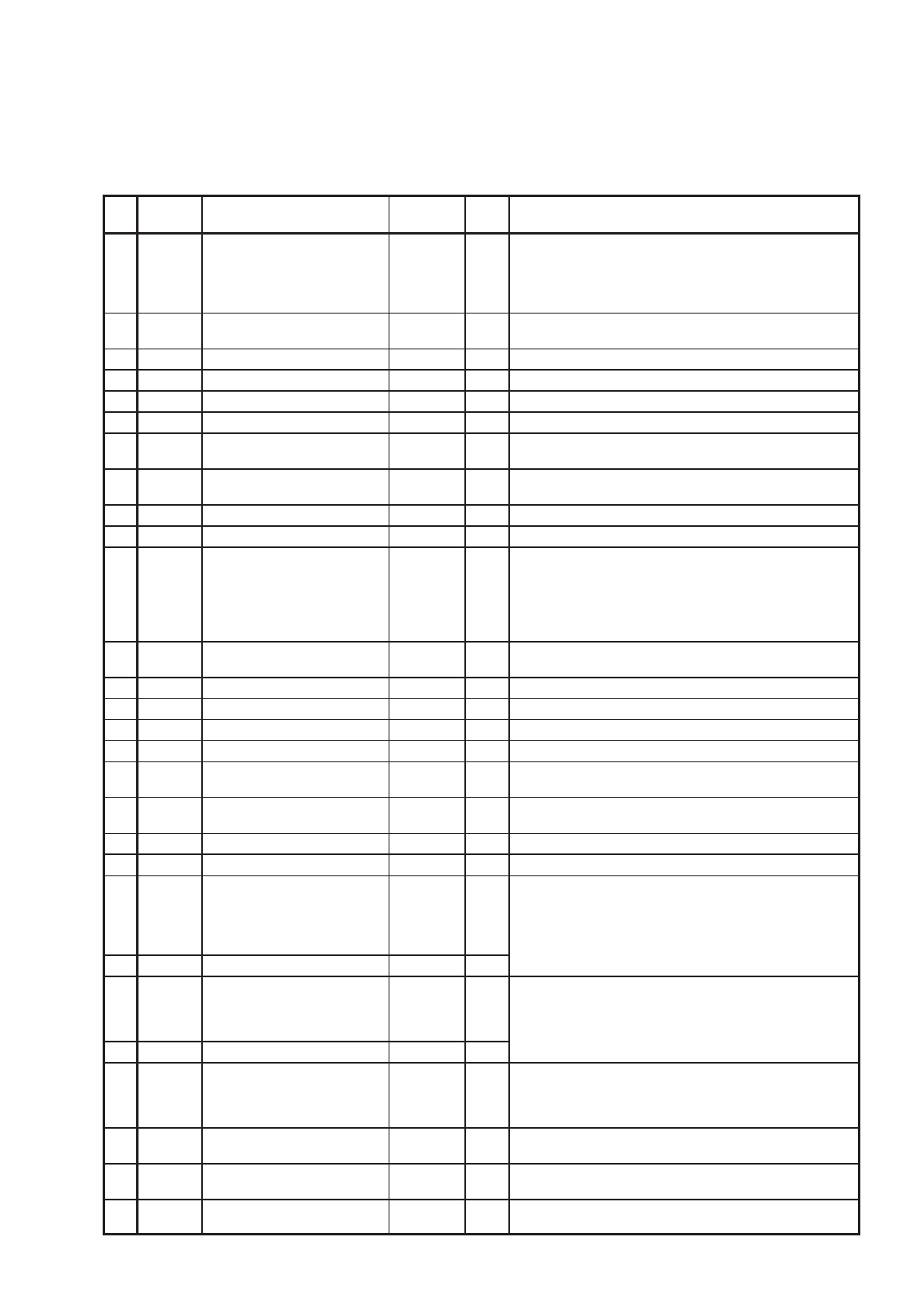
DCP552 Parameter Work Sheet
No. Item code Item
Factory default
User Settings and descriptions
settings
settings
1 C 01 PV1 range number 0 0 to 16 : Thermocouple
48 to 52 : Linear (DC current and DC voltage)
64 to 71 : Resistance temperature detector
96 to 103 : Resistance temperature detector
128 to 134 : Linear (DC current and DC voltage)
2 C 02 PV1 temperature unit 0 0 : Celsius (°C)
1:Fahrenheit (°F)
3 C 03 PV1 decimal point position 1 0 to 2
4 C 04
PV1 linear decimal point position
10 to 4
5 C 05 PV1 linear range lower limit 0 PVU –19999 to +20000 PVU(PV1)
6 C 06 PV1 linear range upper limit 10000 PVU –19999 to +20000 PVU(PV1)
7 C 07
PV1 cold junction compensation
00:Provided (Compensated inside the instrument)
1:Not provided (Compensated outside the instrument)
8 C 08 PV1 root extraction 0 0 : Not provided
1:Provided
9 C 09 PV1 root extraction dropout 0.2 0.2 to 10.0% (Ratio to input range)
10 C 10 PV1 cold junction bias 0.0 –1.0 to + 1.0°C
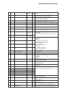
11 C 11 PV2 range number 0 0 to 16 : Thermocouple
48 to 52 : Linear (DC current and DC voltage)
64 to 71 : Resistance temperature detector
96 to 103 : Resistance temperature detector
128 to 134 : Linear (DC current and DC voltage)
135 : O2 sensor (CP)
12 C 12 PV2 temperature unit 0 0 : Celsius (°C)
1:Fahrenheit (°F)
13 C 13 PV2 decimal point position 1 0 to 2
14 C 14
PV2 linear decimal point position
10 to 4
15 C 15 PV2 linear range lower limit 0 PVU –19999 to +20000 PVU(PV2)
16 C 16 PV2 linear range upper limit 10000 PVU –19999 to +20000 PVU(PV2)
17 C 17
PV2 cold junction compensation
00:Provided (Compensated inside the instrument)
1:Not provided (Compensated outside the instrument)
18 C 18 PV2 root extraction 0 0 : Not provided
1:Provided
19 C 19 PV2 root extraction dropout 0.2 0.2 to 10.0% (Ratio to input range)
20 C 20 PV2 cold junction bias 0.0 –1.0 to + 1.0°C
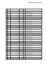
21 C 21 Control output system (CH1) 1 1 : 5G output (Current proportional control output)
2:6D output
(Voltage time proportional control output) system A
3:6D output
(Voltage time proportional control output) system B
4:
8D output (open collector time proportional control output) system A
5:
8D output (open collector time proportional control output) system B
22 C 22 Control output system (CH2) 1
23 C 23 Control action (CH1) 0 0 : PID — A reverse operation
1:PID — A normal operation
2:PID — B reverse operation
3:PID — B normal operation
24 C 24 Control action (CH2) 0
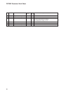
30 C 30 PV equalizer 0 0 : None
1:PV1 only
2:PV2 only
3:Both PV1 and PV2
31 C 31 End of operation (CH1) 0 0 : READY mode
1:END mode
32 C 32 Manipulated variable in READY 0.0 –5.0 to +105.0%
mode (CH1)
33 C 33 Manipulated variable setting 0 0 : No
in PV overrange (CH1) 1 : Yes
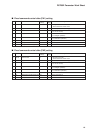
■ Setup data setting