


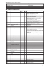
User name : Preparation date :
Equipment name : Product name :
Model No. :DCP552 Tag name :
Instrumentation staffer in charge : Business staffer in charge :
1
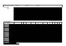
DCP552 Parameter Work Sheet
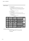
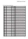
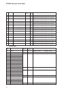
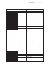
■ Variable parameter setting
No. Item code Item
Factory default
User Settings and descriptions
settings
settings
1 PA 01 Key lock 0 0 : Keylock disabled
1:Display of setup data settings disabled
2:Display of all settings disabled
3:Display of all settings disabled. Operation keys disabled.
2 PA 02 Memory protect 0 0 : Disabled
1:Program settings are protected.
2:Setup, variable parameters and event configuration
settings are protected.
3:Setup, variable parameters, event configurations
and program settings are protected.
4:Setup, variable parameters, event configurations
and PID parameter settings are protected.
5:
Program settings and all parameter settings are protected.
3 PA 03 Display channel setting 0 0 : 2 items are displayed for the selected CH
1:Simultaneous 2CH display of the same item
4 PA 04 Synchronous 2 channel 0 0: asynchronous
operation 1 : synchronous
5 PA 05 Program auto load 0 0 : OFF
1:ON
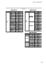
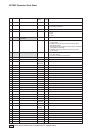
8 PA 08 Auto-tuning (CH1) 0 0 : AT not performed
1:Standard AT performed on currently used PID group
in mode other than READY mode
2:AT writing overshoot-proof PID values to currently used
PID groups in mode other than READY mode performed
3:Standard AT performed on PID groups A1 to A7 in
READY mode
4:AT writing overshoot-proof PID values to PID groups
A1 to A7 in READY mode continuously performed
9 PA 09
Auto-tuning MV lower limit (CH1)
0.0 –5.0 to upper limit %
10 PA 10
Auto-tuning MV higher limit (CH1)
100.0 Lower limit to +105%
11 PA 11 SP bias (CH1) 0 SPU –10000 to +10000 SPU (CH1)
12 PA 12 PV digital filter (CH1) 0.0 0.0 to 120.0sec
13 PA 13 PV bias (CH1) 0 PVU –1000 to +1000 PVU(PV1)
14 PA 14 Manipulated variable deviation 110.0 0.1 to 110.0% OUT / 0.1sec
limit (CH1)
15 PA 15
Time proportional output cycle (CH1)
10 1 to 240sec
16 PA 16 On-off control differential (CH1) 50 SPU 0 to 1000 SPUm (CH1)
17 PA 17 PID computation initialize 0.0 –5.0 to +105.0%
manipulated variable (CH1)
21 PA 21 SP bias (CH2) 0 -10000 to +10000 SPU (CH2)
22 PA 22 PV digital filter (CH2) 0.0 0.0 to 120.0sec
23 PA 23 PV bias (CH2) 0 PVU –1000 to +1000 PVU(PV2)
24 PA 24 Manipulated variable 110.0 0.1 to 110.0% OUT/0.1 sec
deviation limit (CH2)
25 PA 25 Time proportional output 10 1 to 240sec
cycle (CH2)
26 PA 26 ON-OFF control differential 50 0 to 1000 SPU (CH2)
(CH2)
27 PA 27 PID computation initialize 0.0 -5.0 to +105.0%
manipulated variable (CH2)
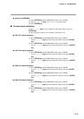
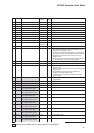
31 PA 31 Group 1 event number 0 0 to 16
(0: No delay is specified.)
32 PA 32 Group 1 delay time 0.0 0.0 to 3000.0sec
33 PA 33 Group 2 event number 0 0 to 16
(0: No delay is specified.)
34 PA 34 Group 2 delay time 0.0 0.0 to 3000.0sec
35 PA 35 Group 3 event number 0 0 to 16
(0: No delay is specified.)